Selection Width Height Example Description
Bar graph 1 display 1 line Shows the weight in pro-
portion to maximum capa-
city.
Fieldbus LEDs ½ Display 1 line --- red --- grn See Chapter 4.6.5.2, for
example.
Fieldbus inputs 1 display 1 line FB-Inp: 01.23...CD.EF Fieldbus inputs
Fieldbus outputs 1 display 1 line FB-Out: 01.23...CD.EF Fieldbus outputs
Digital inputs ½ Display 1 line Inputs: ■□■ Digital inputs: 1, 2, 3
Digital outputs ½ Display 1 line Outputs: ■□■ Digital outputs: 1, 2, 3
Digital I/O ½ Display 1 line I: ■□■ O: ■□■ Digital inputs/outputs:
1, 2, 3
Analog output ½ Display 1 line Ana: 12.345mA Analog output
Limits ½ Display 1 line Limits: ■□■ Limits: 1, 2, 3
Date ½ Display 1 line 2015/09/11 Date
Time ½ Display 1 line 10:37:34 Time
Hostname ½ Display 1 line hopper1 Device name in the net-
work
Hostname (long) 1 display 2 line small material hopper Device name (long)
IP address ½ Display 1 line 192.168.1.1
---.---.---.---
??.??.??.??
Network address
No network
Search DHCP server
IP address (long) 1 display 1 line 172.200.280.255 Network address (long)
Gross (2 lines high) 1 display 2 line B +123.45 kg Gross (2 lines high)
Net (2 lines high) 1 display 2 line NET +123.45 kg Net (2 lines high)
Tare (2 lines high) 1 display 2 line T +123.45 kg Tare (2 lines high)
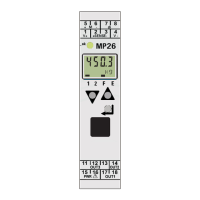
3.4.3.4 LEDs
The instrument has 6 green LEDs for display of the operating or error status.
Display of the operating status
LEDs Hardware error
E:HardE
Bus connection
provided
Bus connection
not provided
Power on Network active
ashing 1 Hz
lit ashing 1 Hz
ashing acc.
lit
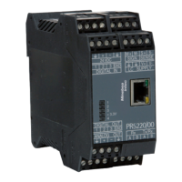
3 Device description Transmitter in eld housing PR 5230
EN-21 Minebea Intec