NOTICE
The rotary switch settings will not be used.
Ensure that the three rotary switches for node address 199 are set to posi-
tion "0."
Settings are dened via - [Fieldbus parameter][Probus-DP].
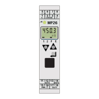
4.6.5.2 Status indicator
Requirements:
- The items are dened via - [Display items]- [Fieldbus LEDs]; see Chapter 7.15.7.
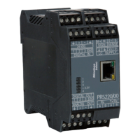
- PR 1721/41 is selected via - [HW-Slots]- [Slot 2].
Display:
1 2 3 4
Constant ---:
No function
Constant grn:
Module is online, da-
ta transmission is
possible.
Flashing 1 Hz red:
Input/output length
conguration error.
Constant red:
Fieldbus is oine,
data transmission is
not possible.
Flashing 2 Hz red:
User parameter error
Flashing 4 Hz red:
Error in ASIC
Legend
--- o
red red
grn green
4.6.5.3 Bus termination
The end nodes in a ProBus-DP network must be tted with termination resistors, to
prevent reections in the bus cable.
Bus termination switch can only be accessed when the device
has been opened.
4 Device installation Transmitter in eld housing PR 5230
EN-81 Minebea Intec