4 Device installation..............................................................................................................................30
4.1 General information.................................................................................................................................................30
4.2 Mechanical preparation...........................................................................................................................................30
4.2.1 General information ......................................................................................................................................30
4.2.2 Cable entry......................................................................................................................................................30
4.2.3 Cabling..............................................................................................................................................................31
4.2.4 Connecting a cable ........................................................................................................................................32
4.3 EMC-compliant installation ....................................................................................................................................32
4.3.1 Connecting the screens.................................................................................................................................32
4.3.2 Connecting the equipotential bonding conductor...................................................................................33
4.4 Hardware construction............................................................................................................................................33
4.4.1 Main board......................................................................................................................................................33
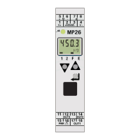
4.4.2 Display board..................................................................................................................................................35
4.4.3 Weighing electronics board .........................................................................................................................35
4.4.4 Network port...................................................................................................................................................37
4.4.5 RS-232 interface.............................................................................................................................................38
4.4.6 RS-485 interface............................................................................................................................................42
4.4.7 Digital inputs ..................................................................................................................................................57
4.4.8 Digital outputs................................................................................................................................................59
4.5 Connecting analog load cells and platforms........................................................................................................64
4.5.1 General information ......................................................................................................................................64
4.5.2 Connecting a load cell with a 4-wire cable.................................................................................................64
4.5.3 Connecting a load cell with a 6-wire cable.................................................................................................66
4.5.4 Connecting 28 load cells (650 Ω) using a 6-wire connecting cable....................................................67
4.5.5 Connecting load cells of type series PR 6221 ............................................................................................67
4.5.6 Testing the measuring circuit ......................................................................................................................68
4.5.7 External supply of the load cells..................................................................................................................68
4.5.8 Connecting 24 load cells via PR 5230/22 load cell junction board ....................................................69
4.5.9 Connecting an analog platform (series CAP…)...........................................................................................71
4.6 Accessories ................................................................................................................................................................74
4.6.1 General information......................................................................................................................................74
4.6.2 Analog outputs...............................................................................................................................................75
4.6.3 Load cell junction board ...............................................................................................................................77
4.6.4 Status LEDs on eldbus card........................................................................................................................78
4.6.5 ProBus-DP interface ...................................................................................................................................78
4.6.6 InterBus-S interface.......................................................................................................................................83
4.6.7 DeviceNet interface.......................................................................................................................................88
4.6.8 CC-Link interface ...........................................................................................................................................92
4.6.9 ProNet I/O interface....................................................................................................................................95
4.6.10 EtherNet-IP interface ....................................................................................................................................98
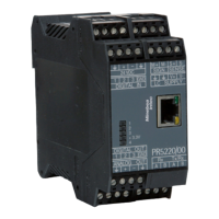
4.6.11 Ethernet port for PR 5230/30.....................................................................................................................101
4.6.12 Ethernet cable for PR 5230/31...................................................................................................................102
Transmitter in eld housing PR 5230 Table of contents
Minebea Intec EN-2