THE MINELAB EXPLORER
17
ASSEMBLY
2
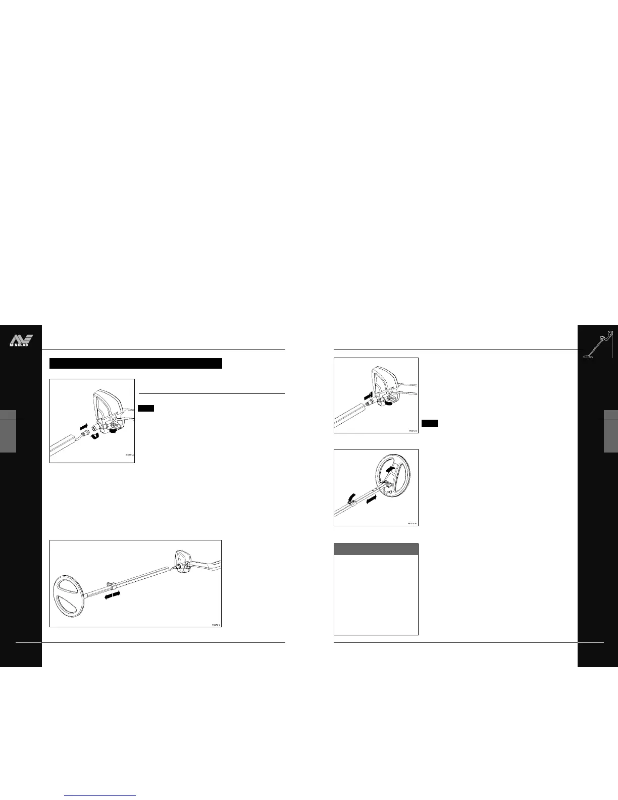
CONNECTING THE SHAFT ASSEMBLY
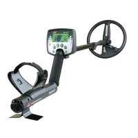
Figure 2.9 Adjusting the shaft and angle of
the search coil
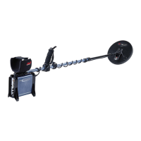
Figure 2.8 Inserting shaft assembly into
control box
Coil not connected?
These instructions require the
search coil to be connected to the
lower shaft. For directions on this
procedure, refer to page 13.
*
STEP 5 Secure upper shaft in position by locking the control box
camlock.
STEP 6 (Figure 2.9) Adjust shaft to the desired length and then lock
with shaft camlock lever.
STEP 7 (Figure 2.9) Tilt the search coil to the most comfortable
angle, keeping in mind it will need to be parallel to the
ground during detecting.
NOTE To avoid difficulty securing the control box camlock
lever, ensure the shaft camlock is released to allow greater
shaft movement.
You are now ready to proceed to the handle assembly.
THE MINELAB EXPLORER
16
ASSEMBLY
2
www.minelab.com
Connecting the shaft assembly to the handle
assembly
Figure 2.6–2.9
NOTE Shaft orientation: coil cable is on bottom of lower
shaft, and camlock is on top of upper shaft.
To connect the shaft assembly to the handle assembly:
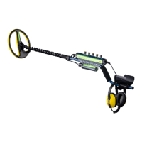
STEP 1 (Figure 2.6) Release the control box camlock lever to the
open position.
STEP 2 (Figure 2.6) Align the connections and push the coil cable
connector into the socket underneath the handle assembly
control box. Ensure the connector’s threaded bracelet is
firmly secured.
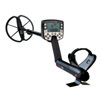
STEP 3 (Figure 2.7) To prevent the coil cable from ‘bunching’,
extend the lower shaft from the upper shaft by approximately
15cm (6 inches).
STEP 4 (Figure 2.8) Making sure that the control box camlock lever
is in the released, push the upper shaft firmly into the control
box until you feel it has reached the back of the control box.
CONNECTING THE SHAFT ASSEMBLY
CONNECTING THE SHAFT ASSEMBLY
Figure 2.6 Attaching coil cable to control box
Figure 2.7 Preventing the coil cable ‘bunching’