8. Navigation and control system
MiR250 User Guide (en) 07/2020 - v.1.2 ©Copyright 2020: Mobile Industrial Robots A/S. 72
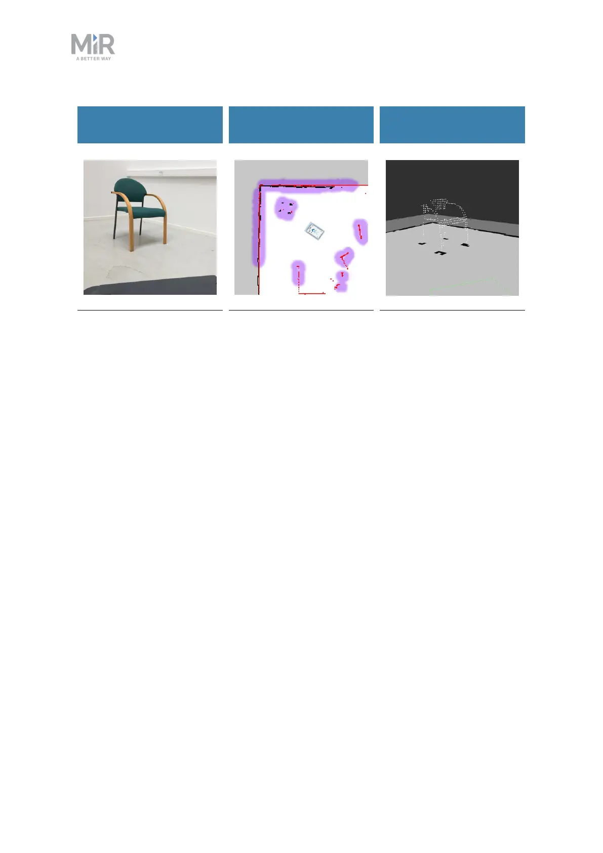
What a human sees
What the laser scanners
see
What the 3D cameras see
A chair placed in the
corner of a room is
detectable by the robot.
In the robot interface, the
red lines on a map are
obstacles detected by the
laser scanners, and the
purple clouds are an
aggregate of the 3D
camera and laser scanner
data. The scanners only
detect the four legs of the
chair.
The 3D cameras detect
more details of the chair
when the robot gets close
enough to it.This view
cannot be seen in the
robot interface.
Safety laser scanners
Two safety laser scanners, diagonally placed on front and rear corners of the robot, scan
their surroundings. Each safety laser scanner has a 270° field of view, overlapping and thus
providing a full 360° visual protection around the robot.
When in motion, the safety laser scanners continuously scan the surroundings to detect
objects.
 Loading...


