8. Navigation and control system
MiR250 User Guide (en) 07/2020 - v.1.2 ©Copyright 2020: Mobile Industrial Robots A/S. 73
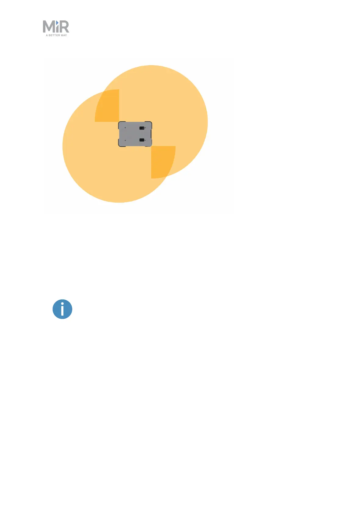
Figure 8.7. The two safety laser scanners together provide a full 360° view around the robot.
The laser scanners have the following limitations:
• They can detect only objects that intersect a plane at 200 mm height from the floor.
• They do not detect transparent obstacles well.
• The scanner data can be inaccurate when detecting reflective obstacles.
If you are using the robot in an area with walls made of glass or reflective
material, mark the wall as a forbidden zone on the map and not as a wall—
see Creating and configuring a map on page104.
3Dcameras
Two 3D cameras positioned on the front of the robot detect objects in front of the robot. The
3D cameras detect objects:
• Vertically up to 1800 mm at a distance of 1200 mm in front of the robot.
• Horizontally in an angle of 114° and 250 mm to the first view of ground.
The 3D cameras are only used for navigation. They are not part of the robot's safety system.
 Loading...


