8. Navigation and control system
MiR250 User Guide (en) 07/2020 - v.1.2 ©Copyright 2020: Mobile Industrial Robots A/S. 75
The 3D cameras have the following limitations:
• They can only detect objects in front of the robot, unlike the full 360° view of the laser
scanners.
• They do not detect transparent or reflective obstacles well.
• They do not detect holes or decending stairways.
• The cameras are not reliable at determining depth when viewing structures with
repetitive patterns.
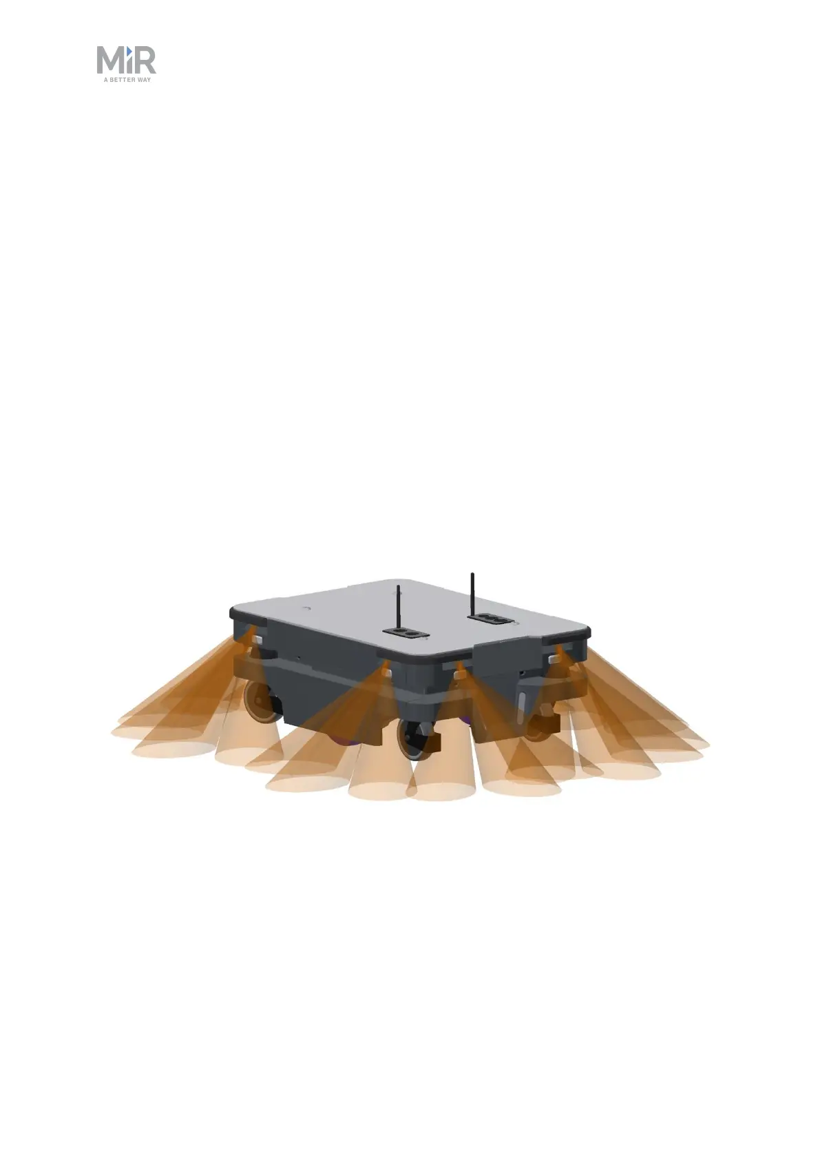
Proximity sensors
Proximity sensors placed in all four corners of the robot detect objects close to the floor that
cannot be detected by the safety laser scanners.
Using infrared light, the proximity sensors point downwards and make sure that the robot
does not run into low objects, such as pallets and forklift forks. They have a range between
5-20 cm around the robot.
Because of the proximity sensor's limited range, the data from them is only useful when the
robot is standing still or moving at reduced speeds.
Figure 8.9. The proximity sensors in the corners of the robot detect objects below the safety laser scanners
plane of view.
The proximity sensors have the following limitations:
• They do not have a long range and are mainly used to detect obstacles missed by the
laser scanners and cameras.
 Loading...


