System Configuration
4
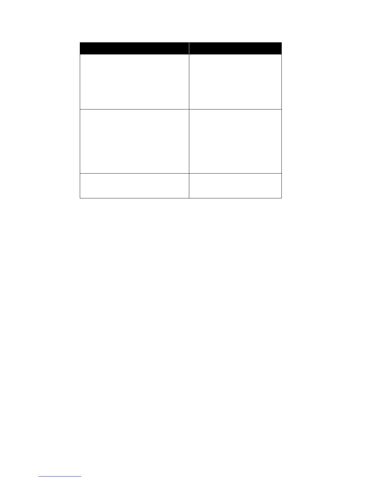
The table below shows the supported devices and process types:
Only the sensors have sensitivity settings and in some cases depend on the setting for drift compensation and the
agency (UL/ULC) selection for which the panel is set up. Drift Compensation is always enabled. The Drift
Compensation feature and algorithm is only applicable for the ion and photo sensor. The multi-sensor has drift
compensation built into the device and the algorithm is not applicable.
The thermal sensor is not affected by the agency (UL/ULC) and/or the drift compensation setting and can be set to
full range.
The devices can be configured to silenceable or non-silenceable and when configured as silenceable the device can
be silenced by activation of the signal silence button.
A “label” is used to identify the device on the shared LCD display and shows a meaningful message when the
device is active or in trouble, the maximum characters allowed for the label is 20. A “label” can be assigned to all
input and output addressable devices and the four on-board NAC circuits.
I/O Correlations
All types of input circuits except remote switches and any of the common system status can be correlated to signals,
strobes, and relays.
By default, the Auto Configure programs new alarm inputs to activate all signals and strobes, and sets the total GA
(General Alarm) Active and Fire Drill Active system status to all signals and strobes. Other input types and status
have no output correlations.
Each input and output may be configured to be "silenceable" or not. For signal and strobe outputs this flag
indicates whether or not the circuit is turned OFF when signal silence is active. For inputs, the silenceable flag
indicates whether or not signals or strobes correlated to that input will be turned OFF when signal silence is active
(providing the output has the silenceable flag set). For relay outputs this flag indicates whether this output is
affected by common auxiliary disconnect.
By default:
• all signals, strobes are silenceable
• all relays are silenceable (affected by auxiliary bypass)
• all verified and non-verified alarms, and GA inputs are silenceable
• all other inputs and all the system status are non-silenceable
DEVICE / ADDER TYPE OPTIONS
SENSORS: analog detector (ion, photo,
multi-sensor and thermal)
Verified alarm
Non-verified alarm
Latching supervisory
Non-latching supervisory
Trouble
Monitor
INPUT MODULES: contact input module
and mini contact input module
Non-verified alarm inputs
Latching supervisory
Non-latching supervisory
Trouble
Monitor
Waterflow
Remote switch
OUTPUT MODULES: relay output
module, supervised output module and
conventional powered output circuit
signals
strobes
relay outputs
 Loading...


