6-540 Interference avoidance function
5Functions set with parameters
(1) Setting the calibration
Set the Base coordinate system origin point for each robot, looking from the common coordinates between
robots, in parameter: RBCORD with the X, Y, Z, A, B and C coordinate values.
Note) When using a locomotion axis, set the positional relation for when the locomotion axis coordinate
value is “0”.
Table 5-40:Set parameters for calibration between robots
(2) Checking the calibration setting results
Check that each robot has been correctly calibrated with the following steps.
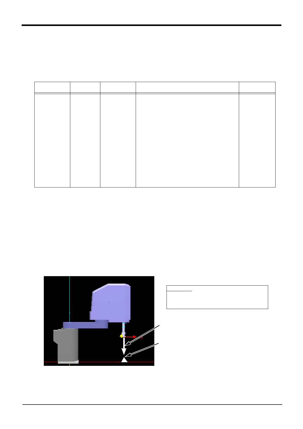
1) Looking at the system layout drawing, etc., set one reference point for each robot. (Fig. 5-26 a) (Here-
inafter, reference point)
2) Move the tip of the robot hand to the set reference point using jog operations.
3) Check the robot (system) status variable: P_CurrR (current robot position looking from common coor-
dinates) using T/B, etc.
4) Compare the above P_CurrR value to the value on the layout drawing, etc.
Only the XYZ values are compared. If the values match, the robot has been correctly calibrated. If the
values do not match, correct the parameter: RBCORD setting value.
5) Carry out the above steps for all robots which are using the interference avoidance function.
Fig.5-26:Checking the setting for calibration between robots
Parameter
Parameter
name
No. of arrays
No. of characters
Details explanation Factory setting
Common coordi-
nates for robots
RBCORD Real number 6 The robot's Base coordinate system origin point looking
from the common coordinates between robots.
(Designate with X, Y, Z, A, B and C coordinate values)
1st element: X-axis coordinate value (mm)
2nd element: Y-axis coordinate value (mm)
3rd element: Z-axis coordinate value (mm)
4th element: A-axis coordinate value (deg)
(Rotation angle around X axis)
5th element: B-axis coordinate value (deg) (Rotation
angle around Y axis)
6th element: C-axis coordinate value (deg) (Rotation
angle around Z axis)
Note 1) For the A, B and C-axis coordinate values
(rotation angles), set the values obtained by
rotating in the order of around Z axis
→ around
Y axis
→ around X axis.
0.00, 0.00, 0.00,
0.00, 0.00, 0.00,
Set to the reference point
Check details
Compare the robot (system) status variable: P_CurrR
and the value from the layout diagram, etc. The set-
ting is correct if the values match.
a) Reference point
Refer to layout drawing,
etc., and determine.
 Loading...