510
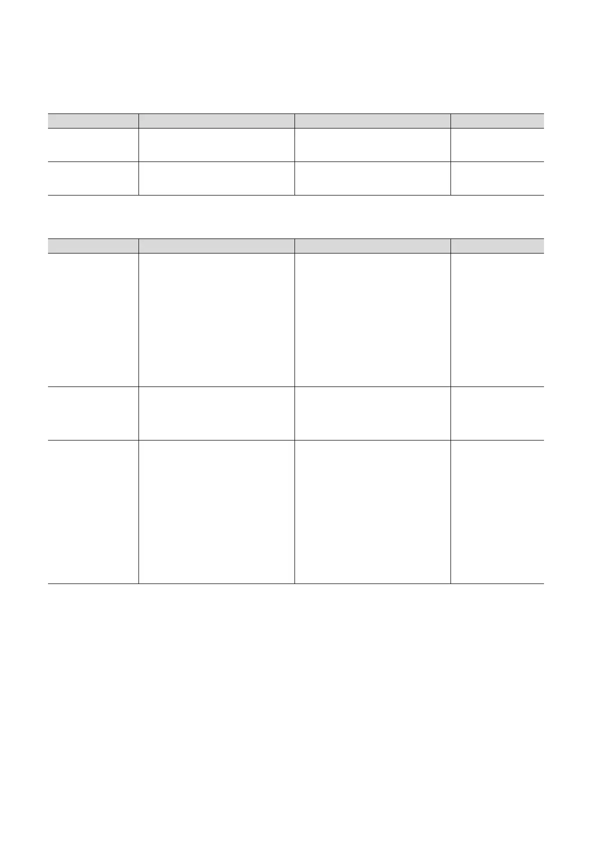
(5) Diagnostic function
(6) Debugging
* 1 Scan time of each program can be checked on the Program monitor list screen.
* 2 Device test can be performed when the modules (Q02UCPU, Q03UDCPU, Q04UDHCPU, Q06UDHCPU,
Q13UDHCPU, and Q26UDHCPU) whose serial numbers (first five digits) are "10041" or earlier are used.
Item Precautions Replacement method Reference
Error history
Error history data cannot be stored in the
memory card.
The Universal model QCPU can store history
data by the number of storable history data in a
memory card (100) to the system memory.
Page 205, Section 3.18
LED indication priority
setting
LED indication priority cannot be set. Only LED
indication setting at error occurrence is
supported.
--- Page 222, Section 3.20.2
Item Precautions Replacement method Reference
Monitor condition setting
To use the monitor condition setting, the
Q10UDHCPU, Q20UDHCPU, Built-in Ethernet
port QCPU, or the modules (Q02UCPU,
Q03UDCPU, Q04UDHCPU, Q06UDHCPU,
Q13UDHCPU, and Q26UDHCPU) whose serial
numbers (first 5 digits) are "10042" or later must
be used.
Check device data under the specified
monitoring condition by using the sampling
trace function when using the Q04UDHCPU,
Q06UDHCPU, Q13UDHCPU, and
Q26UDHCPU. With this function, changes of
the specified device data can be recorded at the
following timings:
• at execution of the specified step
• on the rising/falling edge of bit devices
• when the value of word devices coincide with
the setting value
• at every specified time (settable range: 1 to
5000ms)
Page 146, Section 3.11.1,
Page 184, Section 3.14
Scan time measurement
Time required for executing a part of the
program cannot be measured using the scan
time measurement function.
*1
Calculate the time using instruction processing
time described in the manual.
• Page 181, Section 3.13.3
• Appendix 1 in the
MELSEC-Q/L
Programming Manual
(Common Instruction)
External input/output
forced on/off
To use the external input/output forced on/off
function, the Q10UDHCPU, Q20UDHCPU,
Built-in Ethernet port QCPU, or the modules
(Q02UCPU, Q03UDCPU, Q04UDHCPU,
Q06UDHCPU, Q13UDHCPU, and
Q26UDHCPU) whose serial numbers (first 5
digits) are "10042" or later must be used.
*2
Replace the function by using the programs
described in Page 558, Appendix 5.4.7 when
using the modules (Q02UCPU, Q03UDCPU,
Q04UDHCPU, Q06UDHCPU, Q13UDHCPU,
and Q26UDHCPU) whose serial numbers (first
5 digits) are "10041" or earlier. Note, however,
that replacement method described does not
apply in the following cases:
• Input and output targeted for forced on/off are
referred to or changed using the direct input
device (DX) and direct output device (DY).
• Input and output targeted for forced on/off are
referred to or changed within an interrupt
program.
Page 154, Section 3.11.3,
Page 558, Appendix 5.4.7

 Loading...


