6 INSTALLATION AND WIRING
6.1 Before Using the I/O Modules
71
6
*1 A typical discharge lamp circuit is configured with a combination of discharge tubes, transformers, choke coils, capacitors and others.
Because of this, be especially careful of the case of a high power factor and a low power supply impedance, where the inrush current
flowing into the output module can be 20 to 40 times as high as the rated current.
*2 When the wiring is long, be careful with the cable capacity as well.
■Measures against back EMF
Provide a contact protection circuit for an extended contact life, noise prevention at contact close, and reduction of the
carbides and nitric acids formed by an arc discharge.
An incorrect circuit involves a high risk of contact welding.
With the contact protection circuit, the recovery time may be delayed.
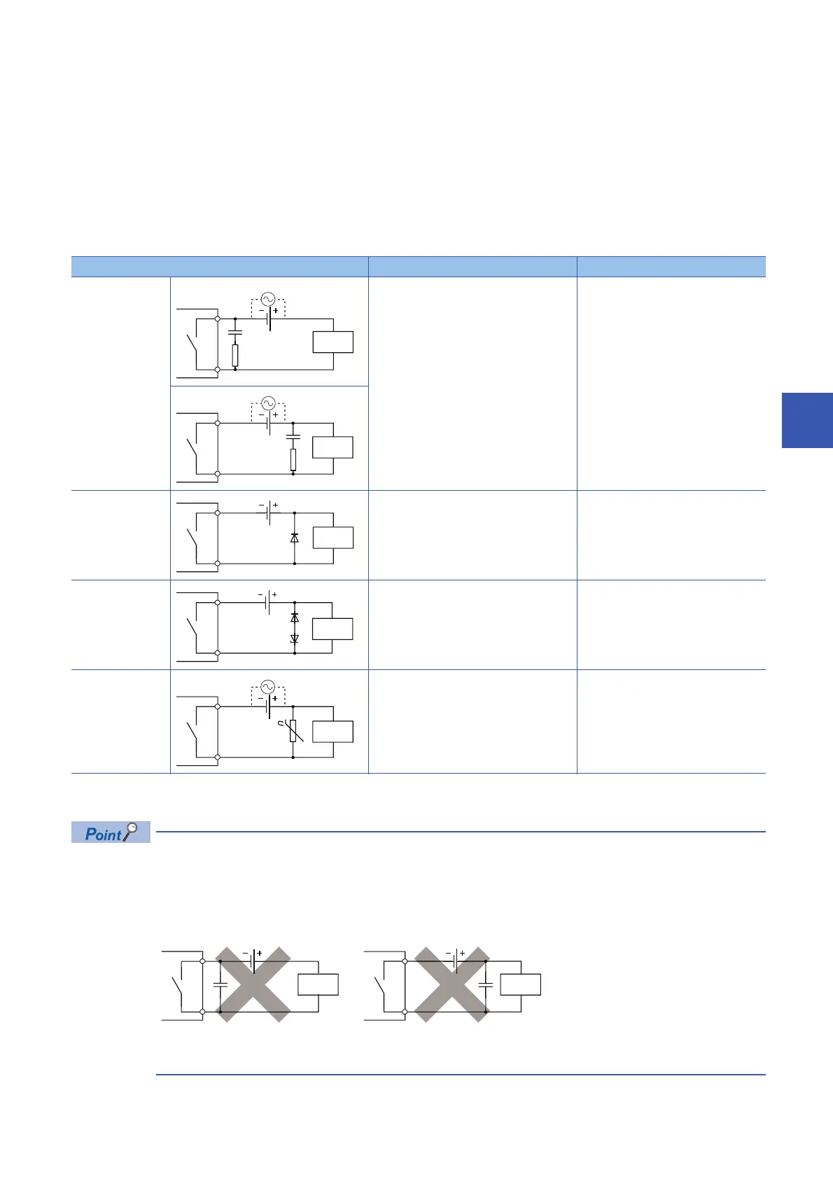
The following table shows typical examples of the contact protection circuit.
*1 On AC power supply, the impedance of the CR needs to be sufficiently higher than that of the load. (for preventing errors due to the
leakage current of the CR).
• Avoid using contact protection circuits like the following. Although they are highly effective in reducing the
arc at current cutoff, a charge current flows into the capacitor when the contact turns on or off, which leads
to the risk of contact welding. A DC inductive load, generally considered to be more difficult to open and
close than a resistive load, can achieve the same performance of a resistive load in an appropriate
configuration of the protection circuit.
• Install the protection circuit near the load or contact (module). A long distance between them may inhibit the
effect of the protection circuit. As a guide, install it at a distance of no more than 50cm.
Circuit example Element selection criteria Remarks
Capacitor +
resistance method
(CR method)
Estimate the constants of a capacitor and
resistance with the following as a guide.
Some differences, however, may arise from a
variation in the nature and characteristics of
the load.
• Capacitor: 0.5 to 1 (F) for a load current of
1A
• Resistance: 0.5 to 1 () for a power supply
voltage of 1V
Use a capacitor whose withstand voltage is
equal to or higher than the rated voltage. In
an AC circuit, use a capacitor with no polarity.
When a relay or solenoid is used as the
load, the recovery time is delayed.
A capacitor has the effect of reducing a
discharge at contact OFF, while a
resistance has the effect of limiting a
current at contact ON.
Diode method Use a diode that satisfies the following
conditions:
• A reverse breakdown voltage is ten or more
times as high as the circuit voltage.
• A forward current is two or more times as
high as the load current.
The recovery time is delayed than the
CR method.
Diode + zener diode
method
Use a zener diode whose zener voltage is
equivalent to or higher than the power supply
voltage.
This method is suitable for the case
where the diode method results in a
substantial delay in the recovery time.
Varistor method Select a varistor whose cut-off voltage (Vc)
satisfies the following condition:
• Vc > Power supply voltage 1.5 (V)
• Vc > Power supply voltage 1.5 (V) 2
(on AC power supply)
Note that selecting an element of an
excessively high Vc leads to a weaker effect.
The recovery time is a little delayed.
Inductive
load
Inductive
load
Inductive
load
 Loading...


