72
6 INSTALLATION AND WIRING
6.1 Before Using the I/O Modules
Precautions when using the transistor output module
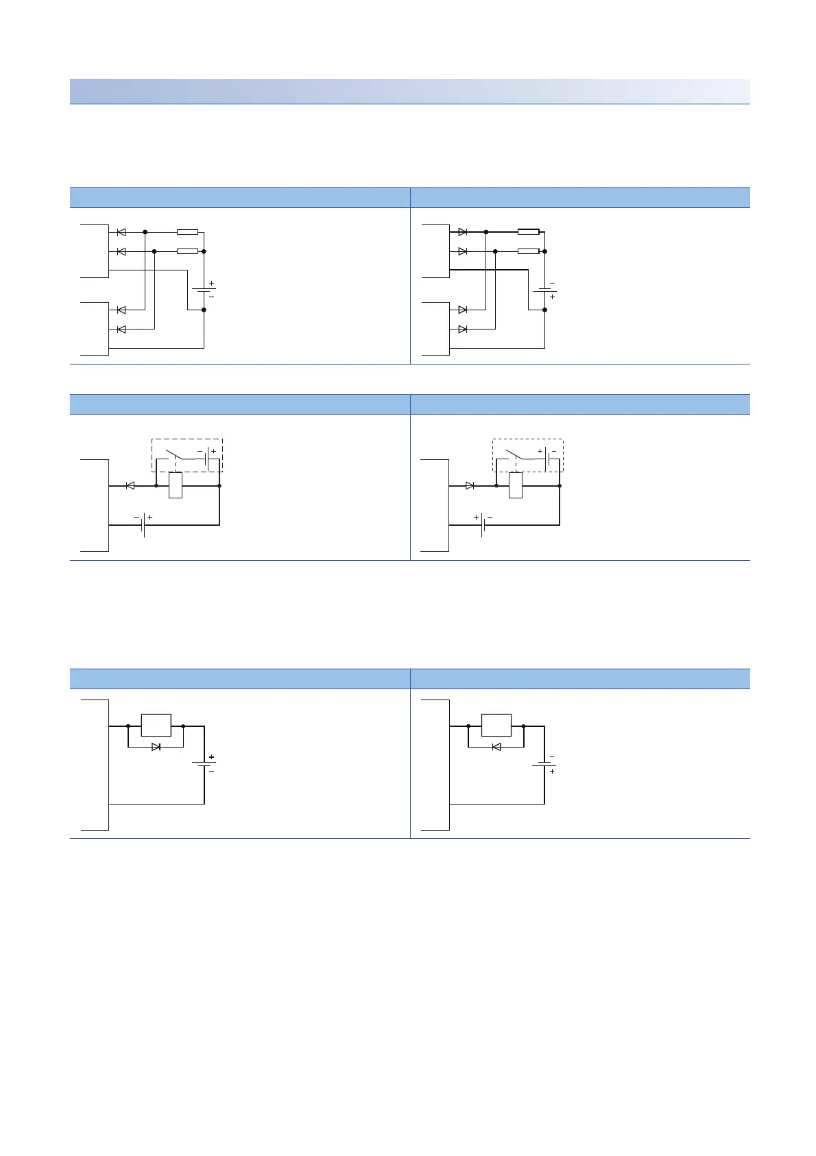
■Measures against reverse current
In the following connections, a reverse current flows to the output element, which can cause failure.
When wiring, set up diodes as the following figures show:
• When connecting transistor output modules in parallel
• When providing another circuit in parallel with a transistor output module
■Measures against back EMF
When connecting an inductive load, connect a diode in parallel with the load.
Use the diode that satisfies the following conditions:
• A reverse breakdown voltage is ten or more times as high as the circuit voltage.
• A forward current is two or more times as high as the load current.
■About element protection of the output module
If excessive noise affects the terminals of the output module, the output may be turned on to help the protection of the output
element. Adjust the voltage between terminals of the output module to fall within the operating load voltage range by taking
measures such as the following:
• To use an inductive load such as a relay, a surge suppressor is required on the load side as well. Take appropriate
measures with the measures against back EMF as a guide.
• To prevent excessive noise, avoid installing power cables together with I/O cables.
Sink type Source type
Sink type Source type
Sink type Source type
OUT1
OUT2
COM
OUT1
OUT2
COM
Load
Load
OUT1
OUT2
COM
OUT1
OUT2
COM
Load
Load
Inductive
load
OUT
COM
Inductive
load
OUT
COM
 Loading...


