6 INSTALLATION AND WIRING
6.5 Wiring
85
6
Wiring of spring clamp terminal block
■Wire to be used
The following table describes the wire to be connected to the spring clamp terminal block.
■Applicable solderless terminal
The following table lists the applicable solderless terminal.
*1 When using a solderless terminal with an insulation sleeve, select the terminal whose applicable wire size is 0.75 or smaller.
*2 Use a bar solderless terminal tool whose manufacturer is the same as that of the bar solderless terminal used.
■Installing or removing the terminal block
The following procedures show how to install and remove the terminal block.
• Lock and release lever positions
To make it easy to install and remove the terminal block, a three-stage positioning stopper is attached so that the lever does
not freely turn around.
When installing or removing the terminal block, turn the lever to the lock or release lever position.
• Removal procedure
Turn the lever to the release lever position and remove the terminal block from the module.
• Installation procedure
Move the lever to the locking lever position and push the terminal block. If the terminal block is fully pushed in, the hook of the
lever hangs on the module and fits the terminal block.
Diameter Type Material Temperature rating
22 to 16 AWG Stranded Copper 75 or more
Product name Model name Applicable wire size
*1
Bar solderless terminal
tool
*2
Contact
Bar solderless
terminal
AI 0.34-10TQ 0.3, 0.34 CRIMPFOX6 PHOENIX CONTACT GmbH & Co. KG
AI 0.5-10WH 0.5
AI 0.75-10GY 0.75
A 0.5-10 0.5
A 0.75-10 0.75
A 1.0-10 1.0
A 1.5-10 1.5
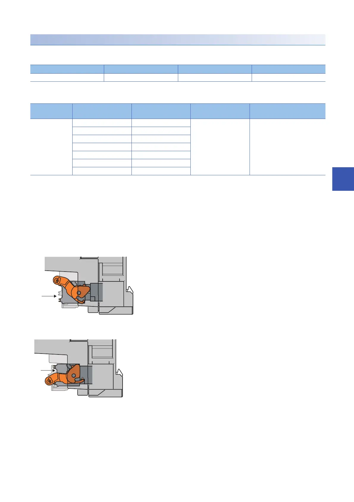
Figure viewed from the module right surface: When pulling the terminal block
1. Release lever position
This lever position shows the state in which the terminal
block (1) has been completely pulled out from the module.
Turn from the locking lever position to the release lever
position (2) and lift the terminal block from the module.
Figure viewed from the module right surface: When insertion of the terminal
block has completed
2. Lock lever position
This position shows the state in which the terminal block (1)
completely fits the module. Check the lock lever position (2)
and pull the terminal block lightly to confirm that the module
completely fits the terminal block.
 Loading...


