EasyManuals Logo

Mitsubishi AL2 Series User Manual

Mitsubishi AL2 Series
152 pages
To Next Page IconTo Next Page
To Previous Page IconTo Previous Page
Page #131 background imageLoading...
Page #131 background image
α2
Simple Application Controllers
Function Blocks 6
6 - 83
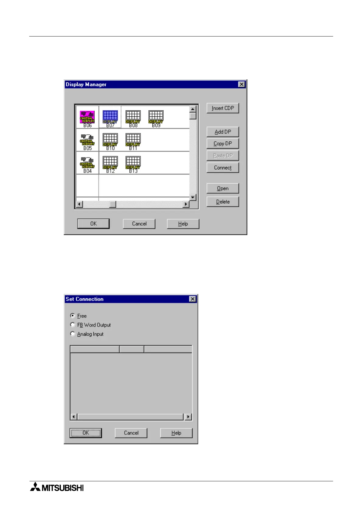
5) Choose the “Display” icon for indication BF (Function Block) or Analog value, and click
“Connect” button.
When not displaying them, please go to step 7)..
6) Click the “Connect” button to display the FB value or the Analog Input value
- Free: Displays the Text, Date or Time. (Default setting)
- FB Word Output: Displays FB value. Choose function blocks from list.
- Analog Input: Displays Analog Input value. Choose Analog Input port.
When completing connection, click the "OK" button.

Table of Contents

Questions and Answers:

Question and Answer IconNeed help?

Do you have a question about the Mitsubishi AL2 Series and is the answer not in the manual?

Mitsubishi AL2 Series Specifications

General IconGeneral
ModelAL2 Series
Digital InputsYes
Digital OutputsYes
TypePLC
ManufacturerMitsubishi
Input Voltage100 to 240 VAC or 24 VDC (depending on model)
Output Voltage24V DC
Number of Inputs8 to 64 (depending on model)
Number of Outputs6 to 64 (depending on model)
Programming LanguageLadder Diagram
Communication PortsRS-232, RS-485, Ethernet (depending on model)
Operating Temperature0 to +55°C
Storage Temperature-20°C to 70°C
Humidity10% to 90% (non-condensing)
WeightVaries depending on the model

Related product manuals