α2
Simple Application Controllers
Function Blocks 6
6 - 33
6.15.2 Editing Data Onscreen
Values in Function Blocks, time, and date can be changed using the front panel keys. During
the function block setup, when the type of data to be shown onscreen is chosen - i.e. Function
Block, Date, or Time - type the “+” key to place the Display Block in the front panel edit mode.
An “e” will appear when the “+” is depressed. When the program is in Run, depressing any key
(that is not used elsewhere in the program) will cause one set of data onscreen to flash. If
multiple entries can be edited, use the arrow keys to choose the data to change.
To edit the time or date, press “OK” key when the appropriate data is flashing. Edit as required
and accept with the “OK” key. To edit the function block values, proceed to the value to be
adjusted as described above. Use the “+” and “-” keys to adjust the value onscreen and in
memory. To exit to the Top Menu, press the “ESC” and “OK” keys simultaneously. The Display
edit mode can be removed from the program by entering the “-” key in the function block setup
when the “e” is flashing. The “e” will disappear when the “-” key is pressed.
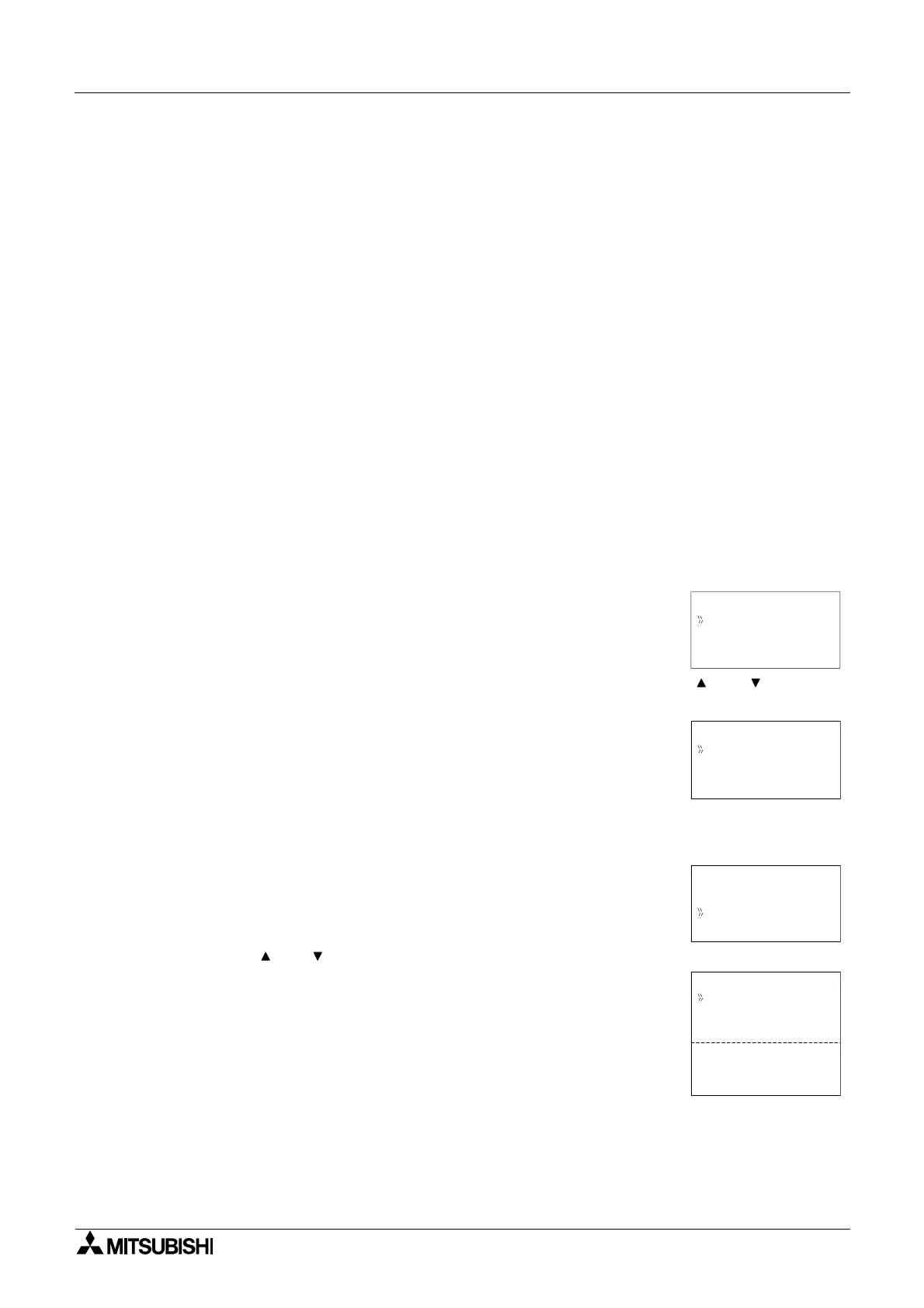
Setup of the Display Function Block directly from the
α2 Series Controller
1 ) Allocate the input or word pin to be used for the function block.
2 ) Press the “OK” key with the cursor in the function block. The function block edit screen is
displayed as shown.
3 ) Press the “OK” Key and enter the function block settings using the “ and ” keys. The
position element and type of data is required.
4 ) Press the “OK” key having highlighted Pos( 1,1) and a X and Y interger can be entered
using the “+” and “-” keys. The X and Y values represent the location coordinates for the
displayed data. Press the “OK” key to accept the coordinate values..
5 ) Using the “ and ” arrows highlight NoData. Press the “OK” key when ready.
B001 : D
Change No
De l e t e FB
P
Se t up FB
Pos ( 1 1,)
B001 : DP
NoDa at
Pos i i no
B001 : DP
X= 21
t
Y= 1
St r i gs
B001 :DP
An l o Ig
n
n
FB V uael
TS D aat
Deat
Teim
a

 Loading...


