α2
Simple Application Controllers
Function Blocks 6
6 - 48
6.20 Pulse Width Modulation
The function block emits a continuous pulse train output when an input is given at a preset
duty cycle.
Table 6.20: Pulse Width Modulation
Note: The ON/OFF time cannot be less than one scan time for the controller; otherwise, the
PWM Function Block will not perform its assigned task for the time specified. Users can
monitor the scan time from the
α2 Series Controller. Scan time is dependent on the user-
program; therefore, caution is needed as and when time units are selected.
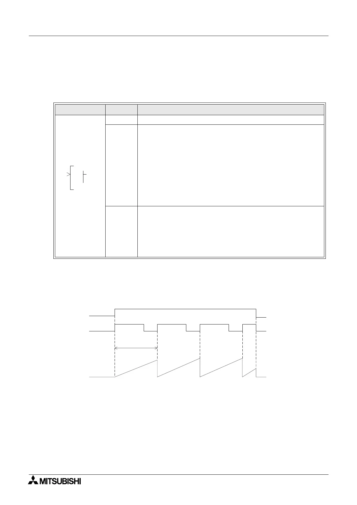
1 ) PWM operation time chart.
Note: 10ms step for minimum resolution.
Function Set Item Description
I Input pin for the pulse width modulation function block
FB
1) The PWM function operates concurrently with the input pin status
set ON.
2) The width of the pulse is dominated by the duty and value of the
period.
3) Duty (setting range:0-100%)
a) Constant Value
b) Analog In
c) FB Value
4) The period is restricted to a setting range: 1 to 32767 x 100ms
(*Note)
Output
The function block is used to control the width of the output pulse
based on a specified period of time and duty.
1) The bit output pin is set on for the length of the duty specified.
2) The following items are available for other function blocks:
a) Set Period
b) Current Period
000
W
P
OI
M
P
Input pin OFF ON
Output pin
OFF ON OFF
Duty: 70%
(ON Time: 70%)
Set cycle
Current value
in cycle
 Loading...


