EasyManuals Logo

Mitsubishi AL2 Series User Manual

Mitsubishi AL2 Series
152 pages
To Next Page IconTo Next Page
To Previous Page IconTo Previous Page
Page #47 background imageLoading...
Page #47 background image
α2
Simple Application Controllers
The Logic Function Blocks 5
5 - 5
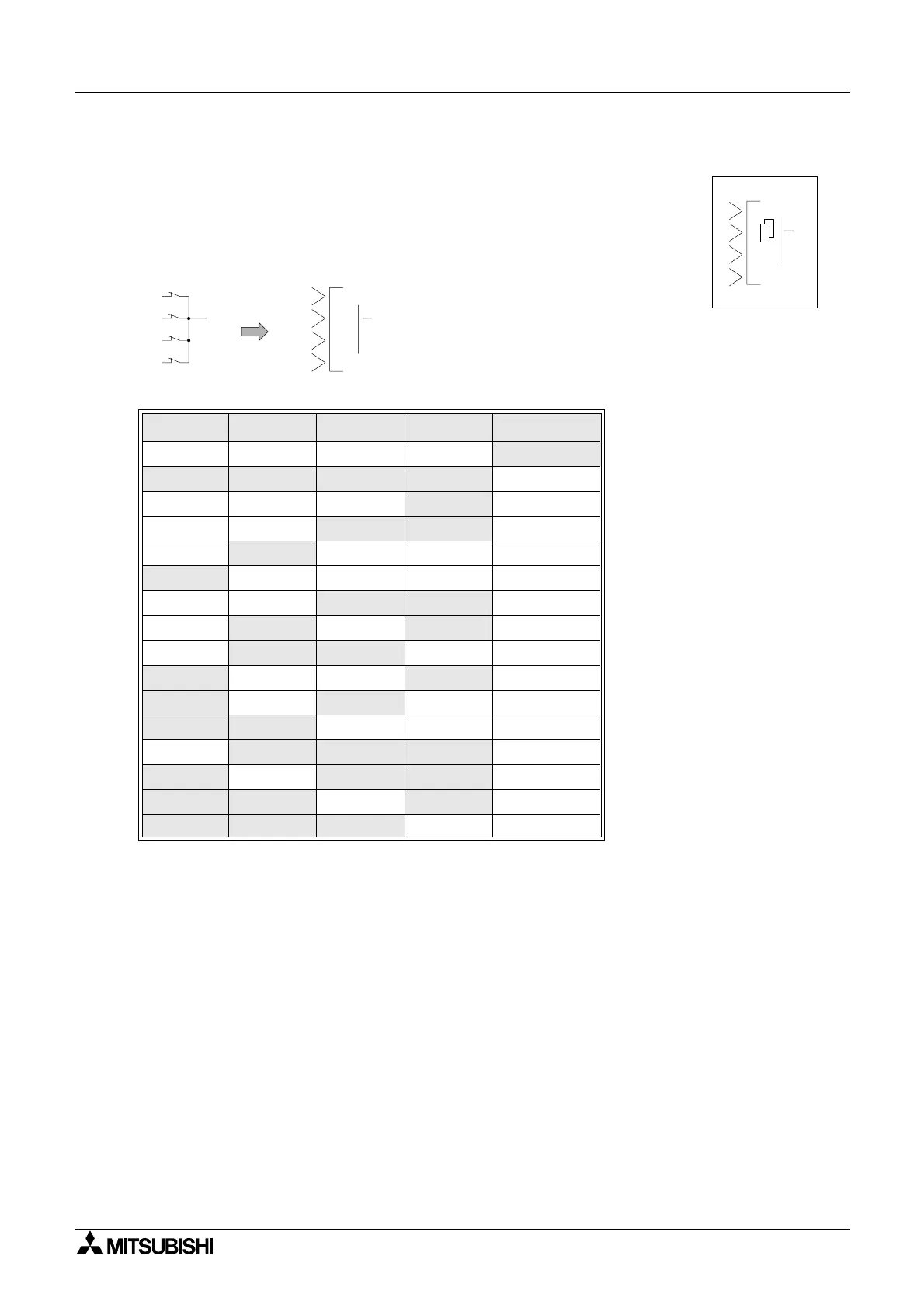
5.5 The NAND Block (Not AND)
The Output comes ON if any or all inputs are OFF.
If every input is ON, the Output turns OFF.
Unused Inputs are considered to be ON.
If no Input pin is used, the block output is OFF.
(This is equivalent to an AND block followed by a NOT block)
.
Table 5.6: NAND Logic gate
Input 1 Input 2 Input 3 Input 4 Output
On On On On Off
Off Off Off Off On
On On On
Off On
On On
Off On On
On
Off On On On
Off On On On On
On On
Off Off On
On
Off On Off On
On
Off Off On On
Off On On Off On
Off On Off On On
Off Off On On On
On
Off Off Off On
Off On Off Off On
Off Off On Off On
Off Off Off On On
00
NAND
2
3
O
4
1
01
NAND
Output
1
2
3
4

Table of Contents

Questions and Answers:

Question and Answer IconNeed help?

Do you have a question about the Mitsubishi AL2 Series and is the answer not in the manual?

Mitsubishi AL2 Series Specifications

General IconGeneral
ModelAL2 Series
Digital InputsYes
Digital OutputsYes
TypePLC
ManufacturerMitsubishi
Input Voltage100 to 240 VAC or 24 VDC (depending on model)
Output Voltage24V DC
Number of Inputs8 to 64 (depending on model)
Number of Outputs6 to 64 (depending on model)
Programming LanguageLadder Diagram
Communication PortsRS-232, RS-485, Ethernet (depending on model)
Operating Temperature0 to +55°C
Storage Temperature-20°C to 70°C
Humidity10% to 90% (non-condensing)
WeightVaries depending on the model

Related product manuals