α2
Simple Application Controllers
Function Block Programming 2
2 - 4
2.1.5 Outputs
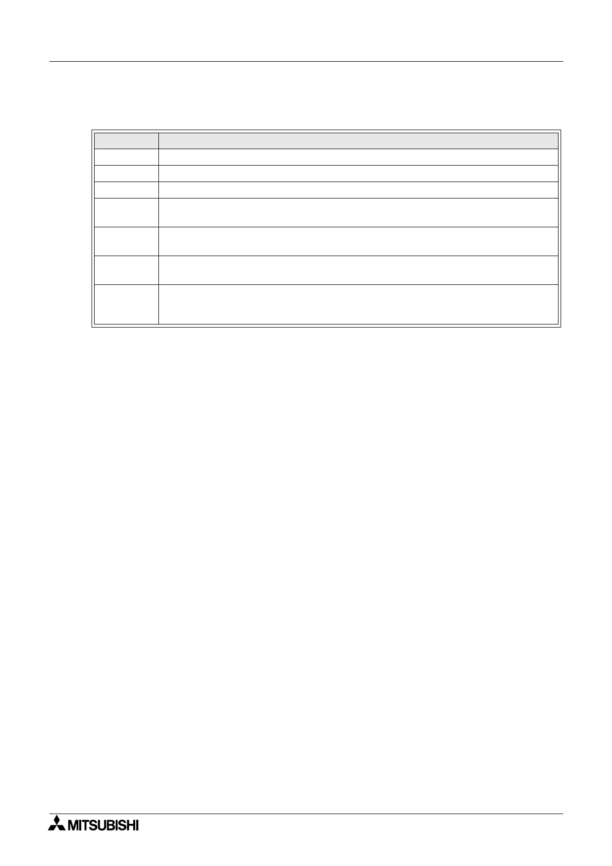
Table 2.4: Outputs for the α2 Series Controller
Note: *1 When both N02 and N03 are ON and hence the back light is “ON” because N03 is
given the priority.
2.1.6 Function Block Diagram (FBD) base
The Function Block Diagram provides the base for which all programming actions for the α2 is
performed. Both the
α2 controller and the AL-PCS/Win-E software use the FBD base. The
FBD base contains a Title rectangle on the top, Input rectangles on the left and Output
rectangles on the right. The FBD base is also known as FBD wiring area. All the components
should be placed only within the FBD base rectangle except for the input and output signals
which can be placed in the FBD wiring area or in the Input or Output rectangles.
Outputs Description
O01 - 09 Signal output
A01 - 04 AS-interface Output
EO1 - E04 Extension Output
N01
ON: Disconnected to AS-interface network
OFF: Connect to AS-interface network
N02*1
ON: The back light is “OFF” in LCD.
OFF: The back light is controlled by the “Light Time” setting in Menu.
N03*1
ON: The back light is “ON” in LCD.
OFF: The back light is controlled by the “Light Time” setting in Menu.
N04
ON: The user screen is controlled by the setting of “Display Manager” with AL-PCS/
WIN-E.
OFF: The user screen is controlled by user program.

 Loading...


