α2
Simple Application Controllers
The Logic Function Blocks 5
5 - 3
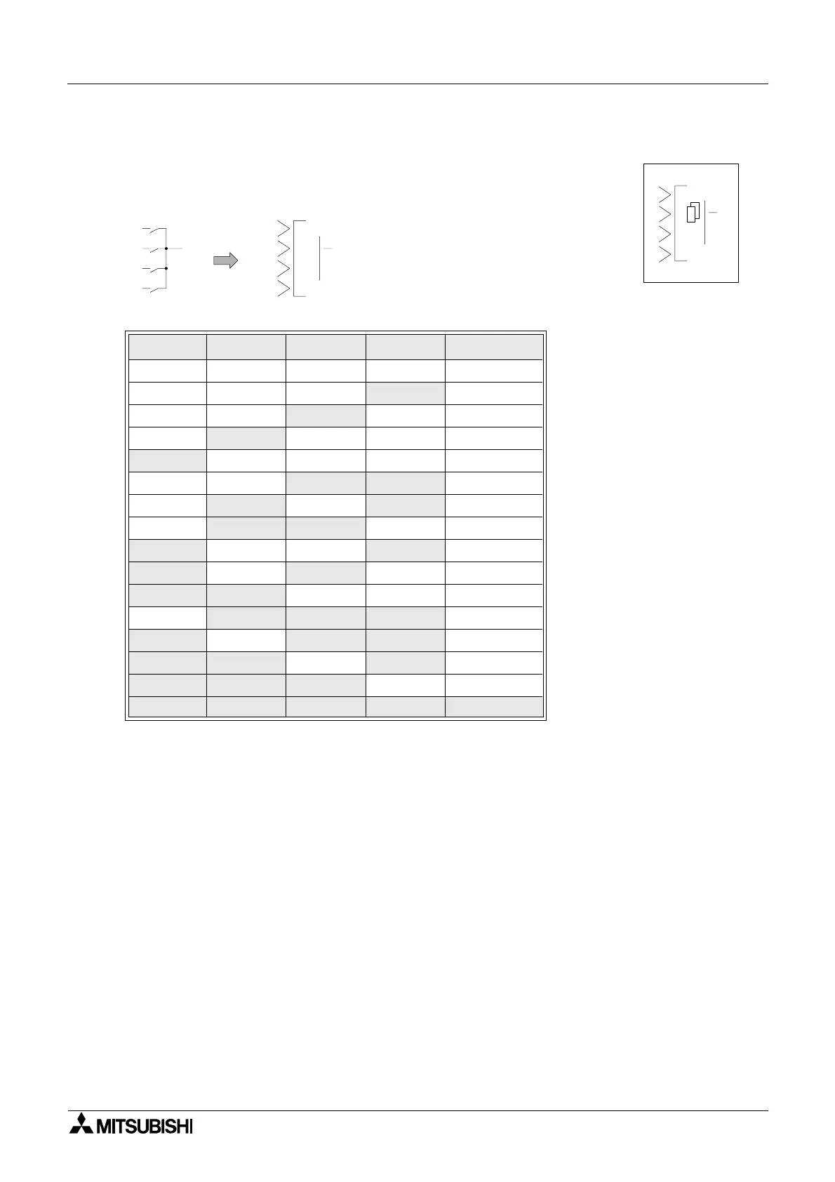
5.2 The OR Block
The Output comes ON when any input is ON.
The Output remains OFF only if all the inputs are OFF.
Unused Inputs are considered to be OFF
Table 5.3: OR Logic gate
Input 1 Input 2 Input 3 Input 4 Output
On On On On On
On On On
Off On
On On
Off On On
On
Off On On On
Off On On On On
On On
Off Off On
On
Off On Off On
On
Off Off On On
Off On On Off On
Off On Off On On
Off Off On On On
On
Off Off Off On
Off On Off Off On
Off Off On Off On
Off Off Off On On
Off Off Off Off Off
00
OR
2
3
O
4
1
01
OR
Output
1
2
3
4

 Loading...


