α2
Simple Application Controllers
Function Blocks 6
6 - 29
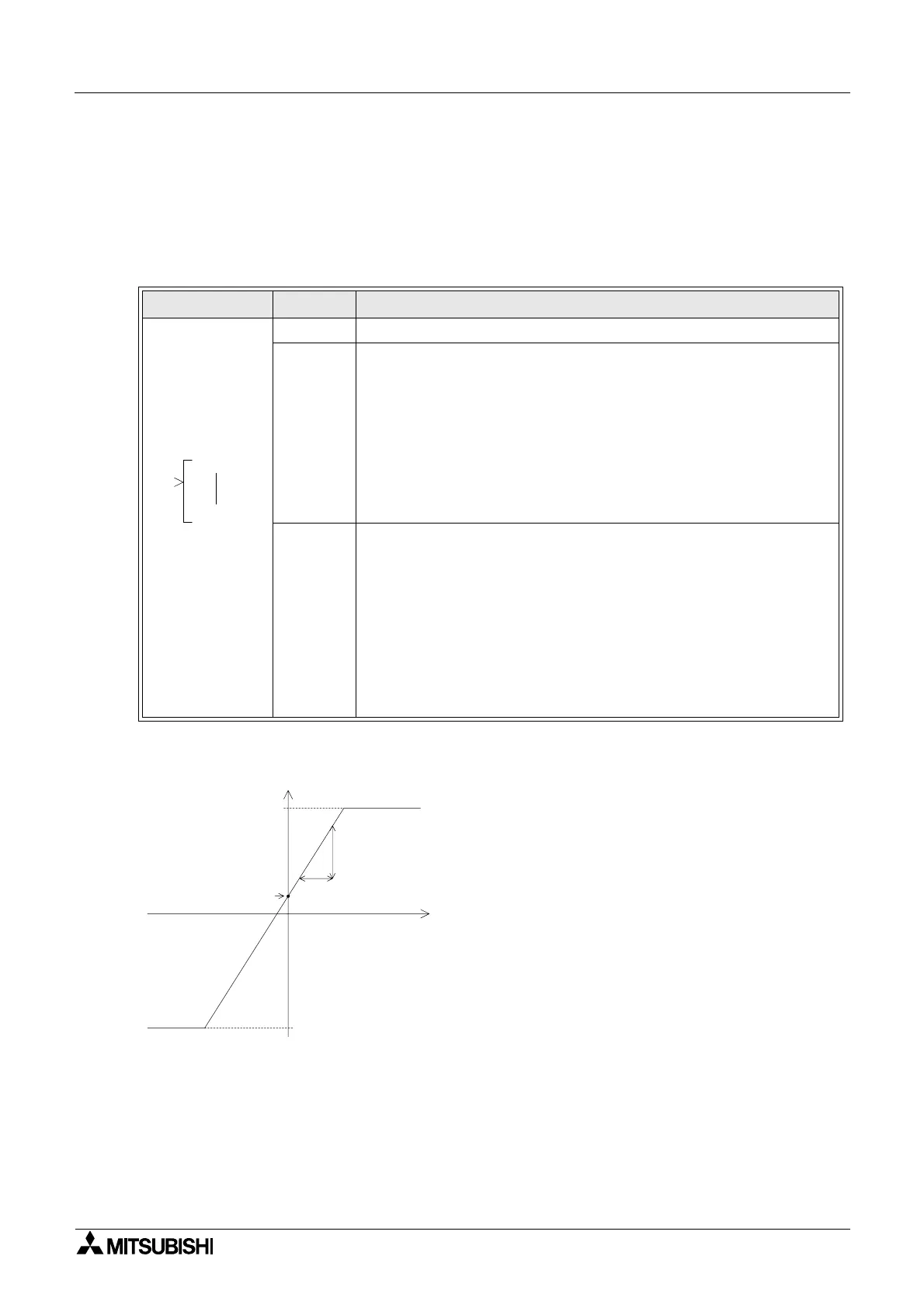
6.14 OFFSET Block
The function block is used to adjust an Analogue Input value according to the following linear
expression: Y=A/B∗X+C from which the values obtained through the analogue input channels
X:A01-A08 are set.
Table 6.14: Offset Gain Function Block
Operation of Offset Gain relationship
Function Set Item Description
I Input pin for Offset Gain operation
FB
1) Setting the operational expression for the linear Y=A/B∗X+C
function
a) Y = Output value
b) A = Gain numerator value set range: -32768 to +32767
c) B = Gain denominator value set range:-32768 to 32767
d) X = Analogue input value from source A01 to A08
e) C = Offset value set range:-32768 to +32767
2) Setting the upper and lower clamp values (limit values)
a) H = Upper Limit set range:-32768 to +32767
b) L = Lower Limit set range:-32768 to +32767
Output
The function block only calculates data.
1) Data output:
a) The resultant of the linear operation is rounded up or down when
the values are within the clamp (limit) values.
b) No signal from the input equates to the function block holding the
previous value obtained from the linear operation.
2) The following items are available for other function blocks:
a) Gain Analog value
000
GO
I P
C
A (numerator of Gain value)
B (denominator of Gain value)
X: Analog input
(A01 to A08)
Lower limit L (Initial value: -32768)
Upper limit H
(Initial value: +32767)
Y: Output

 Loading...


