α2
Simple Application Controllers
Function Blocks 6
6 - 30
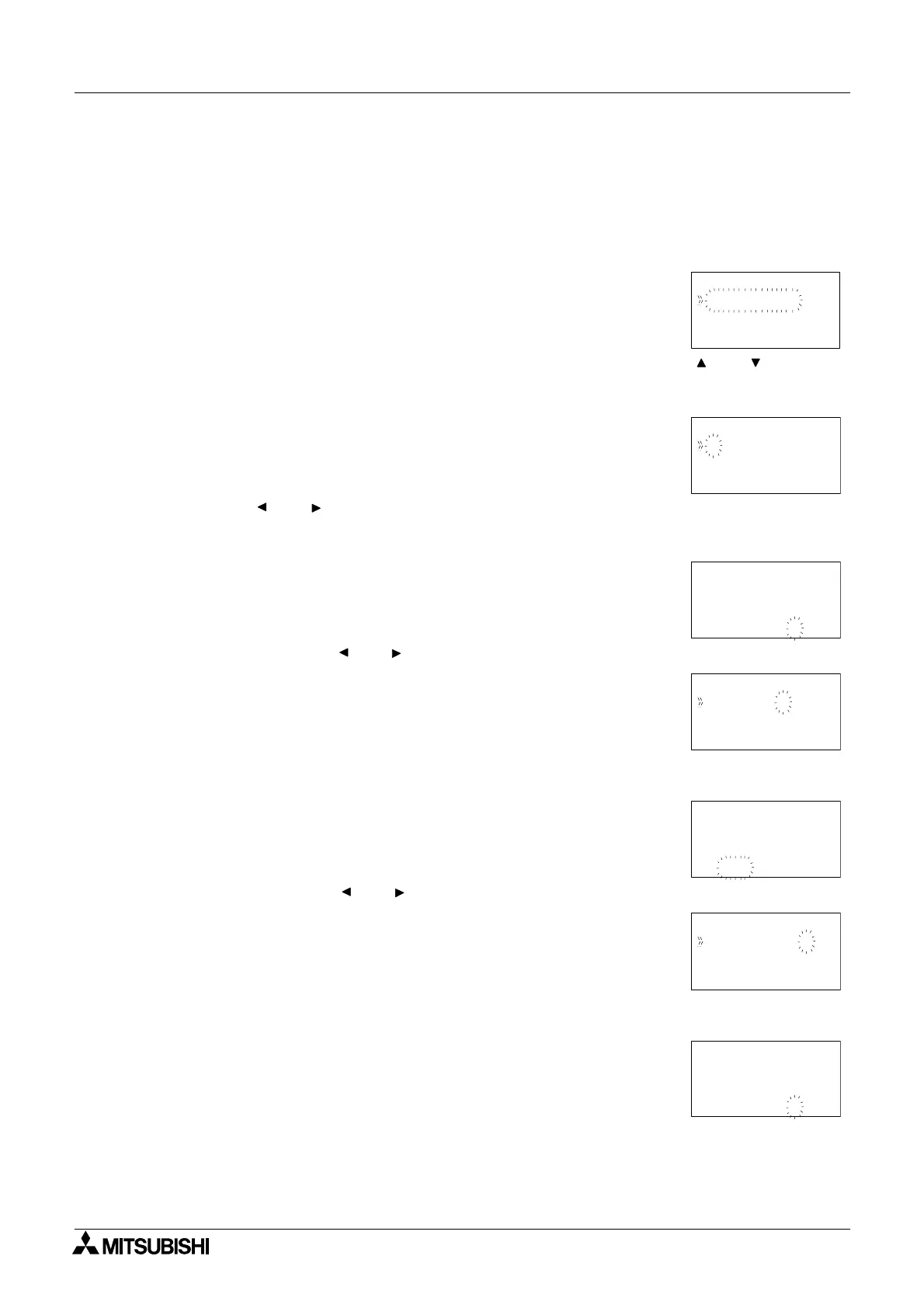
Setup of the Offset Gain Function Block directly from the α2 Series Controller
1 ) Allocate the input pin to be used for the function block.
2 ) Press the “OK” key with the cursor in the function block. The function block edit screen is
displayed as shown.
3 ) Press the “OK” Key and enter the function block settings using the “ and ” keys. The
parameters A, B, X, C, Low limit and High limit have to be specified for the linear
expression to operate correctly..
4 ) Using the “ and ” arrows highlight A and press the “OK” key. A Direct Set using the “+
and -” keys can be entered, subsequently press the “OK” key to accept the Direct Set
value. (Repeat operation for B)
5 ) Highlight X using the “ and ” keys and press the “OK” key to set the Analog In channel.
6 ) The Analog In channel can be selected using the “+ and -” keys, subsequently press the
“OK” key to accept the channel.
7 ) Highlight C using the “ and ” keys and press the “OK” key to set the constant value.
8 ) A Direct Set using the “+ and -” keys can be entered, subsequently press the “OK” key to
accept the Direct Set value.
B001 : OG
Se t up FB
Change No
De l e t e FB
B001 :OG
y=A/B
∗
x
Limi t :L,
+C
H
0
B001 :OG
Con s t an
Di rectSe
tA
t
1
B001 :OG
y=A/B
∗
x
Limi t :L,
+C
H
0
A02 :
B001 :OG
I npu t Va
Ana l og I
l
n
A01 0
B001 :OG
y=A/B
∗
x
Limi t :L,
+C
H
0
B001 :OG
Con s t an
Di rectSe
tC
t
0

 Loading...


