α2
Simple Application Controllers
Function Blocks 6
6 - 43
6.19 Speed Detect Block
The function block measures the signal input frequency for a set user defined period of time.
The frequency is constantly compared to a preset high and low threshold values and the
output is set ON if the conditions are satisfied. The speed detect function block is used to
count incoming pulses, however, for normal inputs without the AL2-4EX expansion module
connected the incoming pulses are restricted to 20Hz. The AL2-4EX, with inputs EI1 or EI2,
expansion module allows for 1KHz incoming pulses to be measured.
Table 6.19: Speed Detect Function Block
Note: The Speed Detect function (SPD) block can use only 1 high speed frequency
(Max.1kHz) in any one program. Subsequent SPD function blocks can only use a
maximum of 20Hz for high speeding counting.
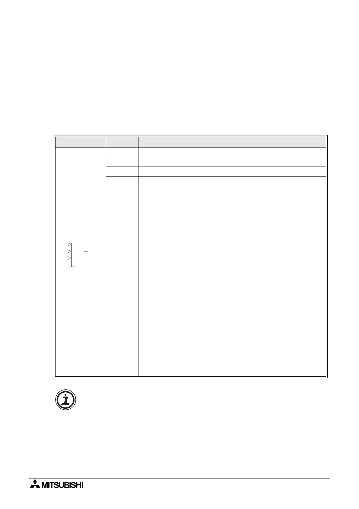
Function Set Item Description
I Input pin for speed detect function block
U Count incoming signal
C Clear pin for function block
FB
The function block counts incoming pulses when the input is ON.
When the input signal is OFF, the actions to count the pulses of the
counter input and compare the speed with upper and lower threshold
limit will stop.
1) Speed and output values will not be cleared unless the clear pin
receives a signal to reset the counter.
2) Upper limit> Lower limit:
The output signal will be OFF when the speed output value is equal to
or less than the lower limit value. If the speed output value is equal to
or larger than the upper limit value the output status will be ON. Oth-
erwise the output signal does not change.
3) Lower limit > Upper limit
The output signal will be OFF when the speed output value is equal to
or larger than the lower limit value. If the speed output value is equal
to or less than the upper limit value the output status will be ON. Oth-
erwise the output signal does not change.
4) Lower limit = Higher limit
The output status is ON if the Speed Output = Lower limit = Upper
limit. Otherwise the output signal is OFF.
5) Function Block data:
a) Period setting value: 1 to 32767
Output
Output status:
refer to the speed detect time charts for output status.
1) The following items are available for other function blocks:
a) Set Period
b) Current Period
000
PS
OU
C
I
D
P

 Loading...


