α2
Simple Application Controllers
The Logic Function Blocks 5
5 - 4
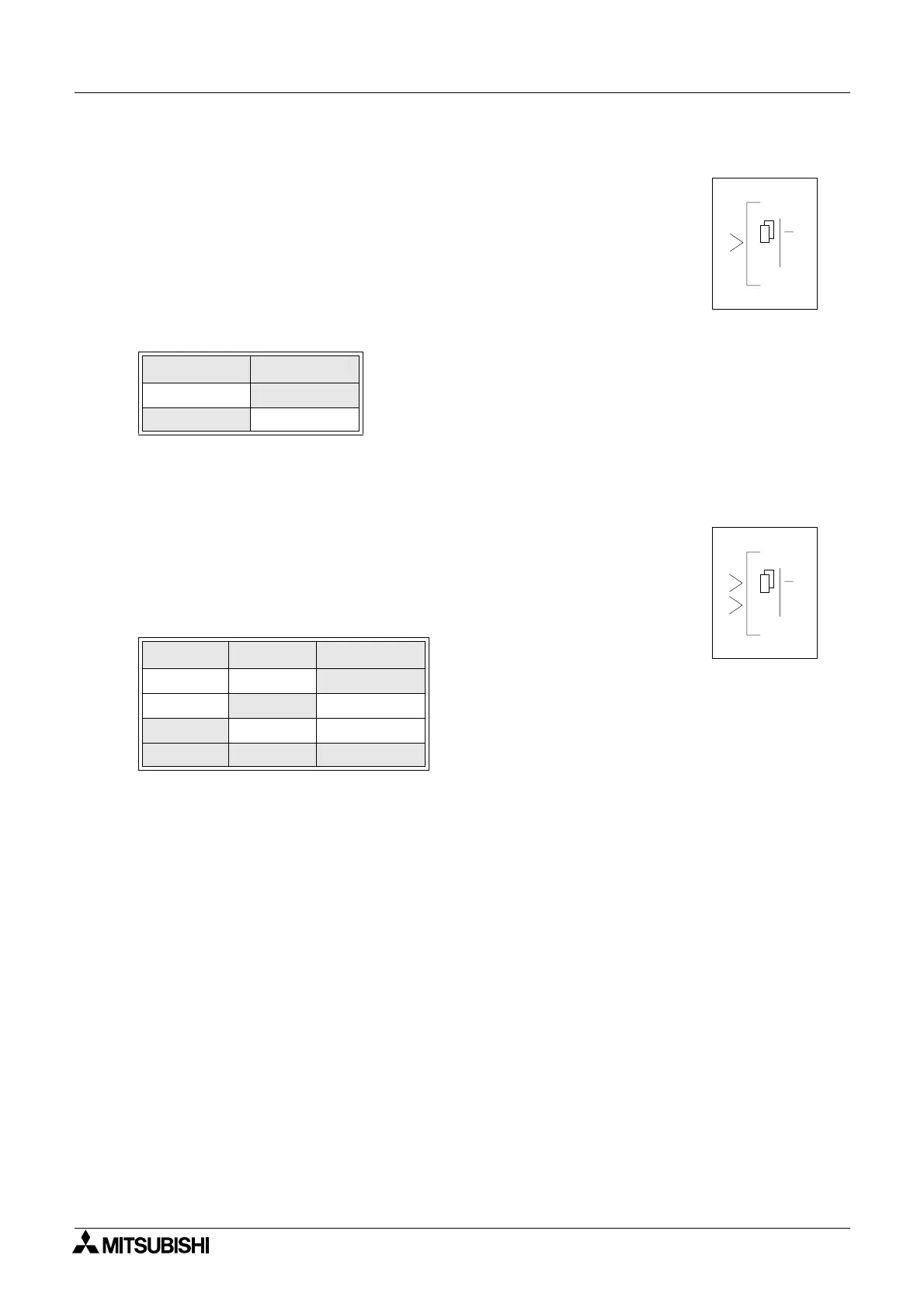
5.3 The NOT Block
The NOT block takes a signal and inverts it - an Input that is ON
has an Output that is OFF, and vice versa.
The Output comes ON when the input is OFF.
The Output is OFF when the input is ON.
If no Input pin is used, the block output is OFF.
The electrical circuit for a NOT block is the same as a Normally
Closed input.
Table 5.4: NOT Logic gate
5.4 The XOR Block (Exclusive OR)
The Output comes ON when one input is ON and one is OFF. The
Output remains OFF when both Inputs are equivalent (either both
ON or both OFF).
Unused Inputs are considered to be OFF.
Table 5.5: XOR Logic gate
Input Output
On
Off
Off On
Input 1 Input 2 Output
On On
Off
On
Off On
Off On On
Off Off Off
00
NT
1
O
00
XOR
1
2
O

 Loading...


