EasyManua.ls Logo

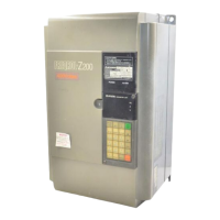
Mitsubishi FREQROL-U100

Mitsubishi FREQROL-U100
90 pages
To Next Page IconTo Next Page
To Previous Page IconTo Previous Page
Loading...
Terminal
wiring
diagram
Inverter
FR-U100
F".
0'
NFB
3-phase AC
(Note 3)
2OO~~";;~Vu:)$OHl,
2OOV50Hz
R
(Note 4) 200 to 220V60Hz
(
UL tYpe is 200V. 50HZ)
S
200 to 230V. 60Hz
_-"'_--<10
T
u
V
W
Motor
1M
Control input signal
*2
(Voltage cannot be input)
~-----------
-------,
:
Forwerd
STF *1 :
:
Rlverse
l-
..........J STR '
,
frPra
ntact
:
, common
I
,
------------
B
-e-Aterm
output
C
_(Contact
output)
Grounding
mill]
Key pad
10(+5V)
2(Oto5V)
5 (common)
FreqUenC\
setting signal
*3
(analog
~--------------'
: 3 :
, 2
: 1
: Frequency setter *4
,
(l/2W
1kO
: Characteristics
, curve B) :
,---------------
@Terminal
for
main circuit
Olnput
terminal
for
control circuit
.Output
terminal
for
control circuit
Single-phase fuse
AC power supply or
)
100V50Hz
~FB
(Note 1 100to 110VSOHz R
(
UL type is 100to)
S
115V. SO/SOHz
(Note2)
2oo2~~~2g~OOHZ
(
UL type is 200
to)
230V.
50/S0Hz
-52-

Table of Contents

Related product manuals