INSPECTION AND REPAIR OF BASIC ENGINE
6-16
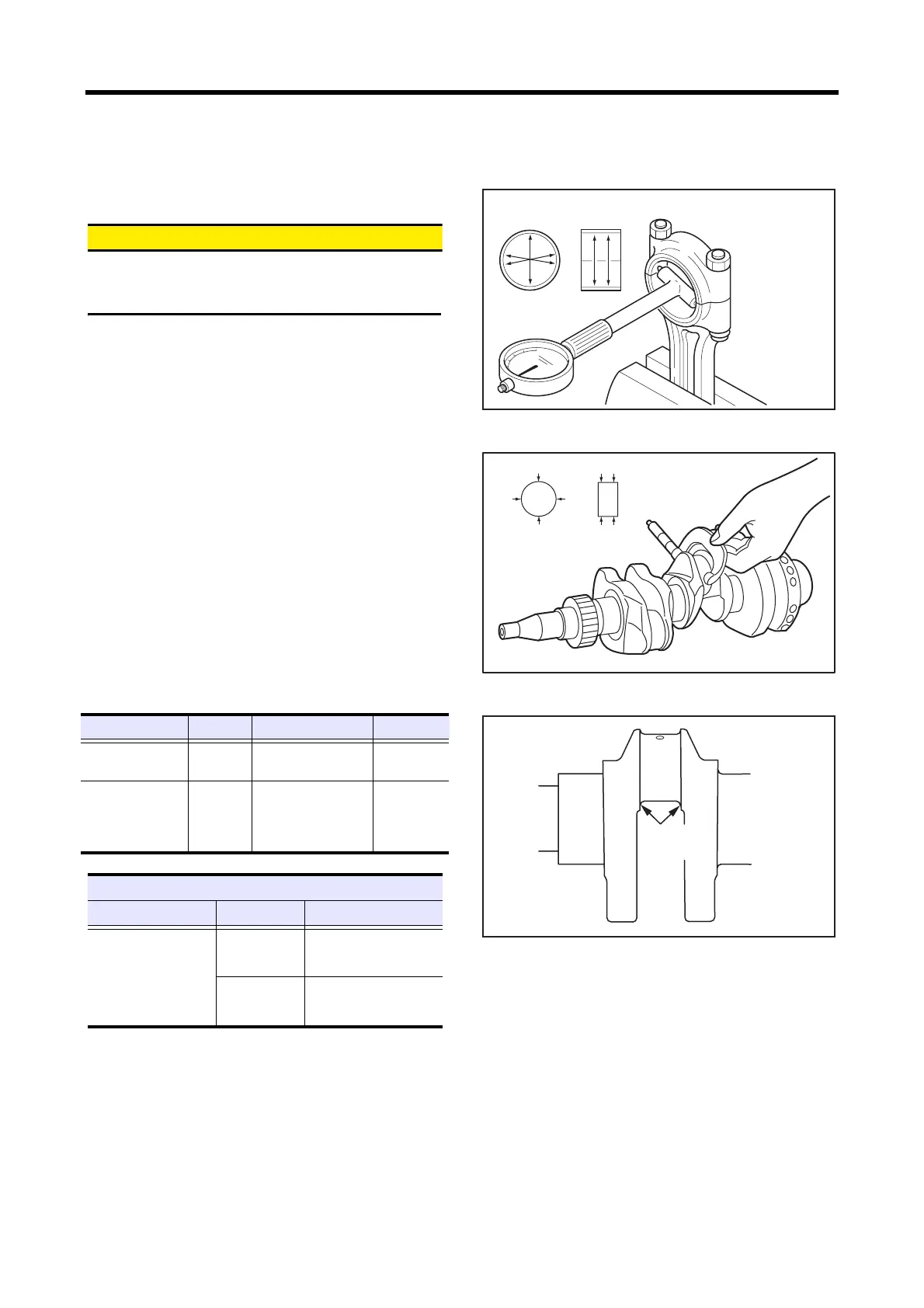
4.8 Measuring clearance between connecting
rod bearing and crankpin
&$87,21
When grinding crank pins, be sure to grind all the pins
to the same size.
Finish the fillet radius to the specified dimension.
(1) Reassemble the bearing into the big end of the
connecting rod.
(2) Tighten the connecting rod cap bolts to the specified
torque.
(3) Measure the inside diameter of the connecting rod
bearing.
(4) Measure the outside diameter of the crank pin.
(5) Calculate the clearance from the difference between the
inside diameter of the connecting rod bearing and
outside diameter of the crank pin.
(6) Replace the connecting rod bearing if the clearance
exceeds the limit.
(7) Measure the clearance between the connecting rod
bearing and the crank pin again. Use the undersize
bearing if the limit is exceeded.
(8) If an undersize bearing is used, grind the crank pin to
the specified undersize.
Measuring inside diameter of connecting rod bearing
Measuring crank pin outside diameter
Finish dimension of fillet radius
Item Nominal Standard Limit
Crankpin outside
diameter (STD)
ø 40 mm
[1.57 in.]
39.965 to 39.980 mm
[1.5734 to1.5740 in.]
-0.70 mm
[-0.0276 in.]
Clearance between
crankpin and
connecting rod
bearing
-
0.028 to 0.071 mm
[0.0011 to 0.0028 in.]
0.150 mm
[0.0059 in.]
Undersize grinding dimensions of crankshaft
Item Undersize Finish dimension
Crankpin undersize
0.25 mm
[0.0098 in.]
ø 39.75
-0.035
-0.020
mm
[1.5650
-0.0014
-0.0008
in.]
0.50 mm
[0.0197 in.]
ø 39.50
-0.035
-0.020
mm
[1.5551
-0.0014
-0.0008
in.]
Measuring
directions
Measuring
points
Tightening torque
31.4 to 34.3 N㨯m
{3.2 to 3.5 kgf㨯m}
[23.1 to 25.3 lbf㨯ft]
Measuring
directions
Measuring
points
R2
0
-0.2
mm
[0.08
0
-0.008
in.]
 Loading...


