M800S/M80/E80 Series Connection and Setup Manual
4 General Specifications
95
IB-1501269-J
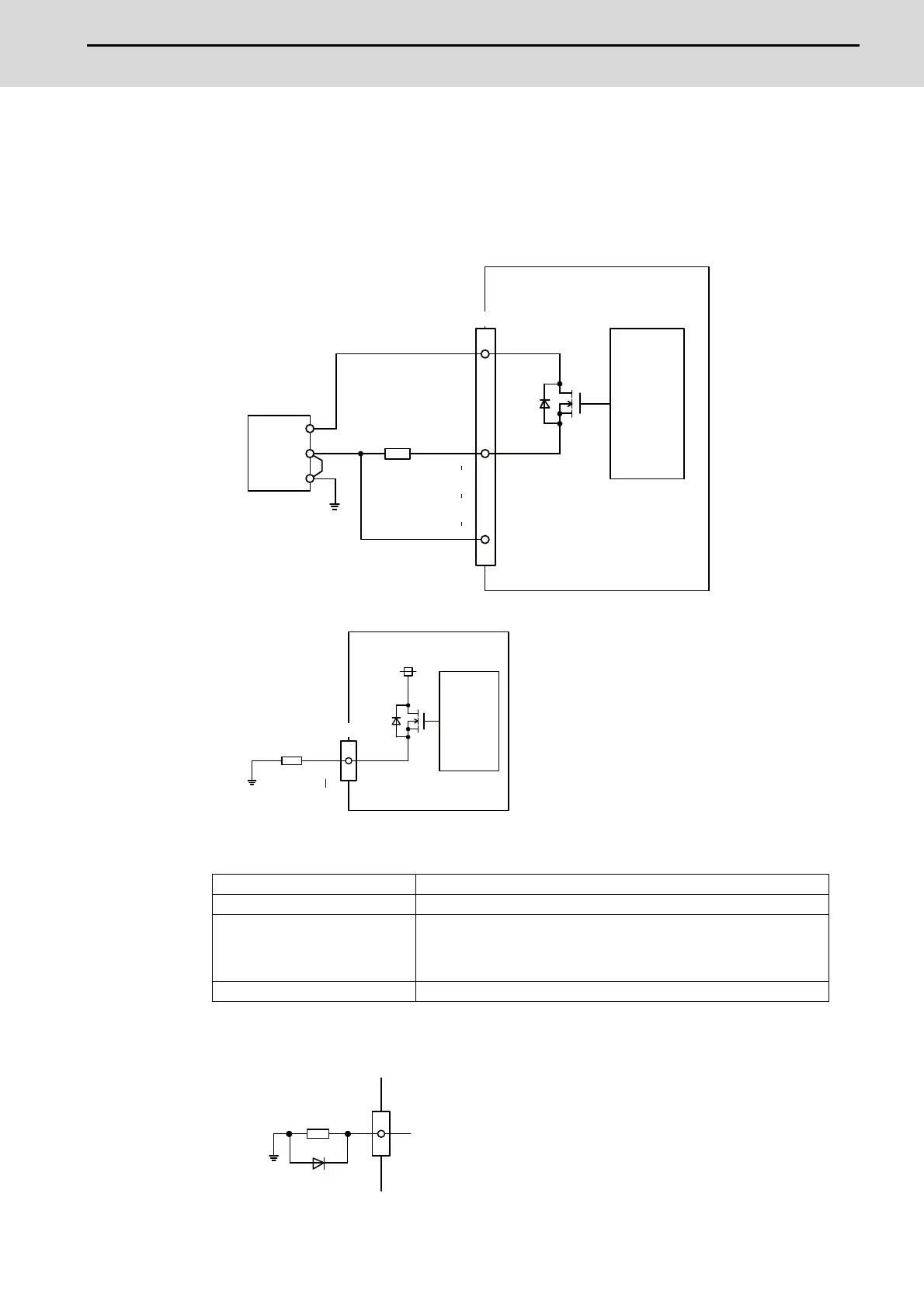
(a) Outline of digital signal output circuit
Use within the specification ranges shown below.
Output circuit
[FCU8-DX731 / FCU8-DX750 / FCU8-DX760 / FCU8-DX761]
[FCU8-DX834]
Output conditions
(Note 1) When using an inductive load such as a relay, always connect a diode (voltage resistance 100V or
more, twice or more the load current) in parallel to the load.
Insulation method Non-insulation
Rated load voltage 24VDC
Max. output current
0.2A/point
[Total output current of whole unit]
- For FCU8-DX731/DX750/DX761/DX834: 3.8A or less
- For FCU8-DX760: 5.7A or less
Output delay time 40μs
DOCOM
0V
0V
FG
Y200
Y23F
CG32/CG36/CJ38/CJ40/CJ42
Y260
Y27F
Y240
Y24F
24VDC(+)
Control
circuit
Stabilized
power supply
Load
Source output
Y200
Y23F
CG32/CG34
24VDC
Load
Control
circuit
Source output
Y
Source output
Inductive load
Diode

 Loading...


