M800S/M80/E80 Series Connection and Setup Manual
4 General Specifications
121
IB-1501269-J
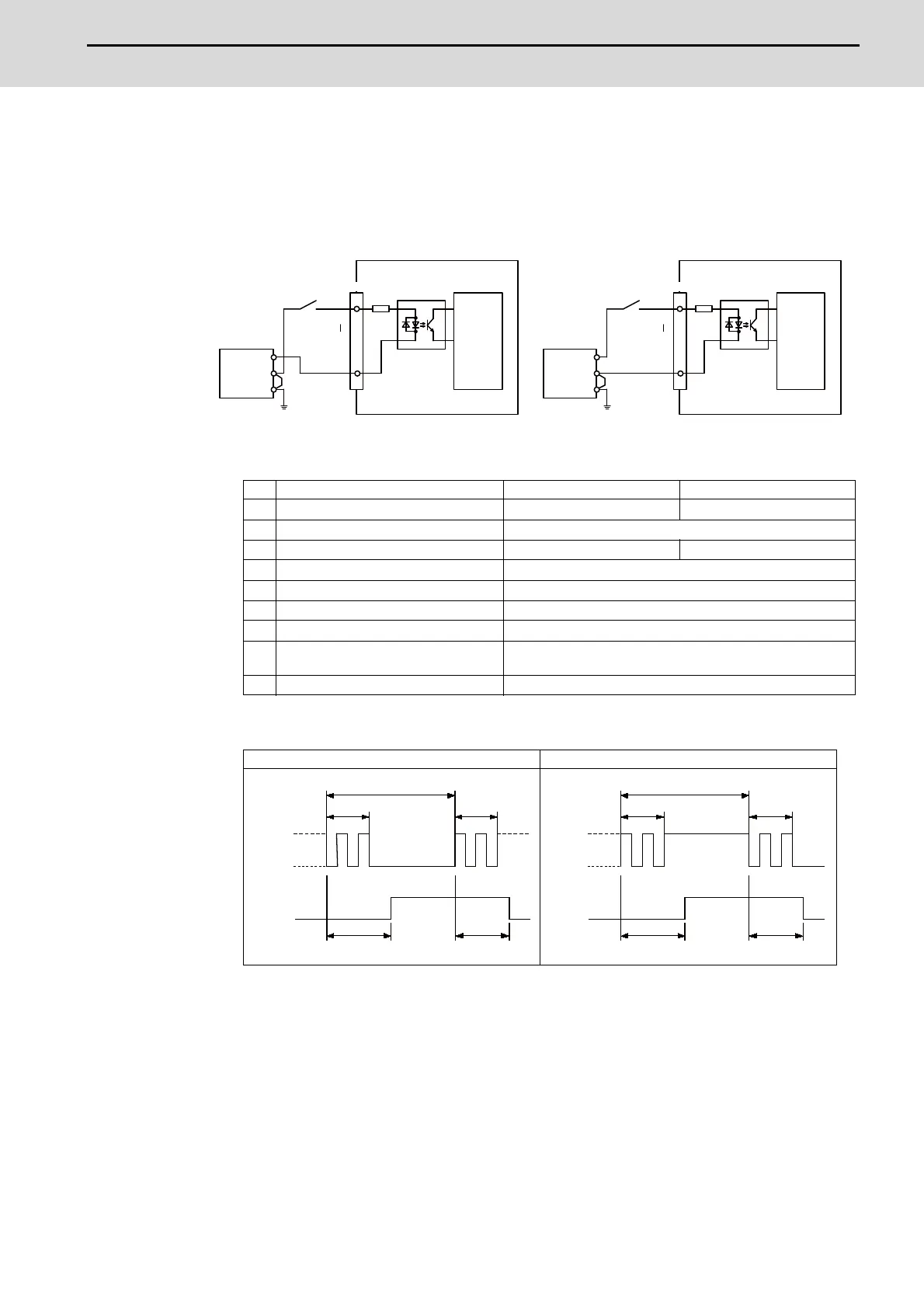
(a) Outline of digital signal input circuit
Both 24V common and 0V common connections are allowed in the digital signal input circuit.
Follow the wiring diagram below for each type.
Input circuit
Input conditions
The input signals must be used within the following condition ranges.
(*1) Note that "40 ms or more" is a guide of the "Input signal holding time". The input signal is
recognized only when its "ON" state is held longer than the ladder processing cycle time.
(E) : External signal, (I) : Internal signal
24V common 0V common
1 Input voltage at external contact ON 6V or less 18V or more, 25.2V or less
2 Input current at external contact ON 3mA or more
3 Input voltage at external contact OFF 20.2V or more, 25.2V or less 3.8V or less
4 Input current at external contact OFF 0.7mA or less
5 Input resistance 5kΩ
6 Tolerable chattering time (T1) 3ms
7 Input signal holding time (T2) 40ms or more (*1)
8
input circuit operation delay time (T3
and T4)
3 to 16ms
9 Machine side contact capacity 30V or more, 16mA or more
Connection to 24V common input Connection to 0V common input
X00
X3F
0V
FG
5kΩ
DICOM
X00
X3F
0V
FG
5kΩ
DICOM
24VDC(+)
24V common
Control
circuit
Stabilized
power supply
External contact
24VDC(+)
0V common
Stabilized
power supply
External contact
Control
circuit
CJ31/CJ33CJ31/CJ33
T1T1
T2
GND
+24V
T4T3
(E)
(I)
T1T1
T2
T4T3
GND
+24V
(E)
(I)

 Loading...


