M800S/M80/E80 Series Connection and Setup Manual
4 General Specifications
123
IB-1501269-J
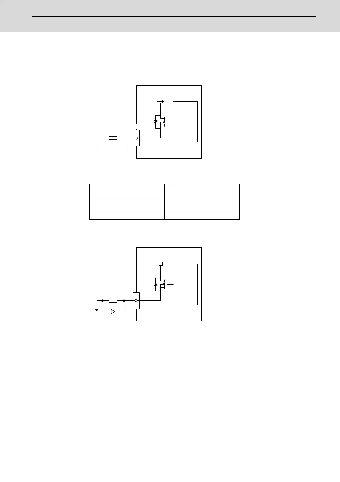
(a) Outline of digital signal output circuit
Use within the specification ranges shown below.
Output circuit
Output conditions
(Note 1) When using an inductive load such as a relay, always connect a diode (voltage resistance
100V or more, twice or more the load current) in parallel to the load.
Insulation method Non-insulation
Rated load voltage 24VDC
Max. output current
0.2A/point
3.2A or less in the whole unit
Output delay time 40μs
Y00
Y2F
CJ32/CJ34
24VDC
Load
Source output
Control
circuit
Y
24VDC
Source output
Control
circuit
Inductive load
Diode

 Loading...


