M800S/M80/E80 Series Connection and Setup Manual
4 General Specifications
127
IB-1501269-J
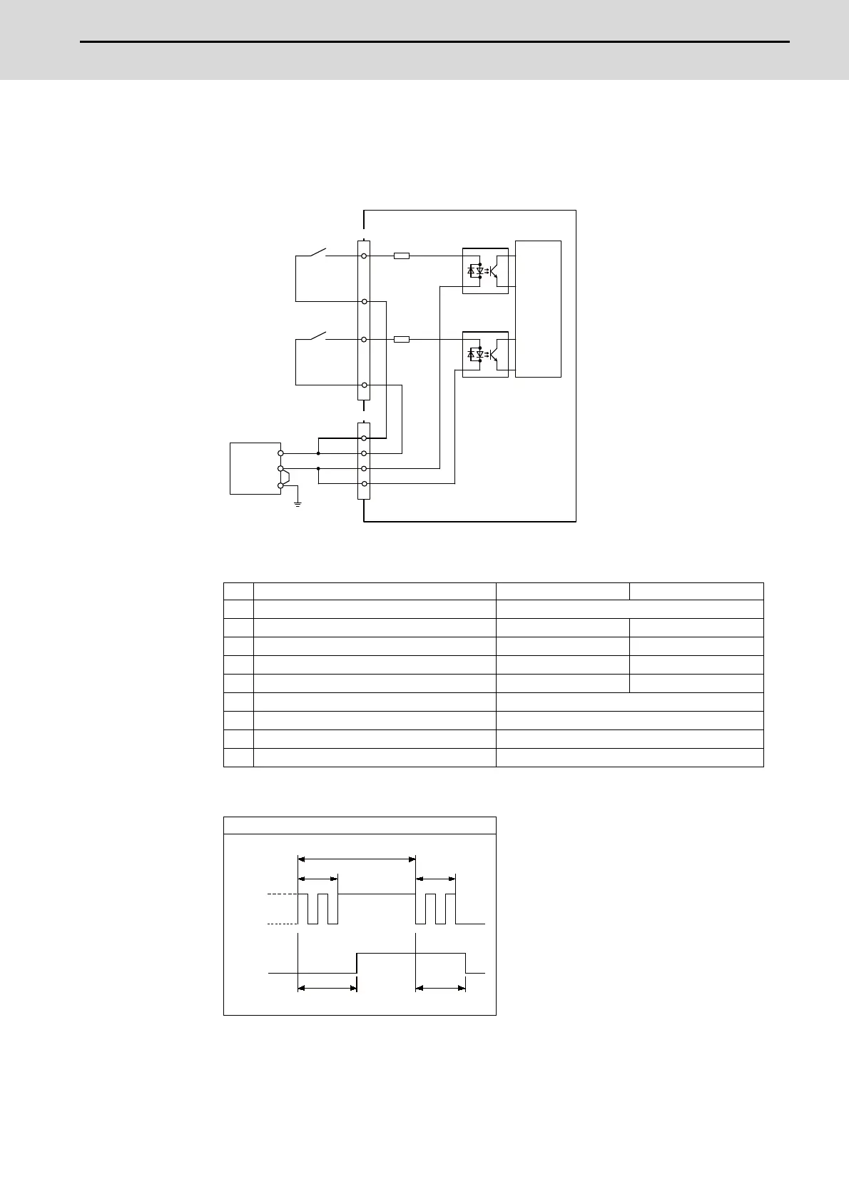
(a) Outline of digital signal input circuit
Follow the wiring diagram below.
Input circuit
Input conditions
The input signals must be used within the following condition ranges.
(*1) Note that "40 ms or more" is a guide of the "Input signal holding time". The input signal is
recognized only when its "ON" state is held longer than the ladder processing cycle time.
(E) : External signal, (I):Internal signal
For DX213 For DX213-1
1 Input voltage at external contact ON 18V or more, 25.2V or less
2 Input current at external contact ON 3mA or more 9mA or more
3 Input voltage at external contact OFF 3.8V or less 4.0V or less
4 Input current at external contact OFF 0.7mA or less 1.5mA or less
5 Input resistance (*) 5kΩ 2.2kΩ
6 Tolerable chattering time (T1) 3ms
7 Input signal holding time (T2) 40ms or more (*1)
8 input circuit operation delay time (T3 and T4) 3 to 16ms
9 Machine side contact capacity 30V or more, 16mA or more
Connection to 0V common input
X0
X2
XE
CJ35
COMA+
CJ36
IO0VB
IO24VA
IO0VA
IO24VB
X1
X3
XF
COMB+
|
|
0V
FG
Input
resistance
(*)
External contact
External contact
Stabilized
power supply
0V common
Control
circuit
24VDC(+)
Input
resistance
(*)
T1T1
T2
T4T3
GND
+24V
(E)
(I)

 Loading...


