M800S/M80/E80 Series Connection and Setup Manual
22 Setting the Position Detection System
475
IB-1501269-J
(7) Turn the power OFF and ON, and then execute reference position return.
(8) Confirm the grid space and grid amount values on DRIVE MONITOR screen.
If the grid amount value is approximately half of the grid space, the grid mask amount has been set correctly. If the
value is not approximately half, repeat the procedure from step (1).
(9) Set the reference position shift amount (#2027 G28sft).
To designate the electrical zero point as reference position, set "#2027 G28sft" to "0".
(10) Turn the power OFF and ON, and then execute the reference position return.
(Note) The axis moves at the speed of "#2025 G28rap G28 rapid traverse rate".
The parameter "#2025 G28rap G28 rapid traverse rate" is usually set the maximum speed, which makes
the high-speed movement in the 2nd reference position return and later. Take extra care for the safe axis
movement.
(11) Set the machine coordinate system offset amount (#2037 G53ofs).
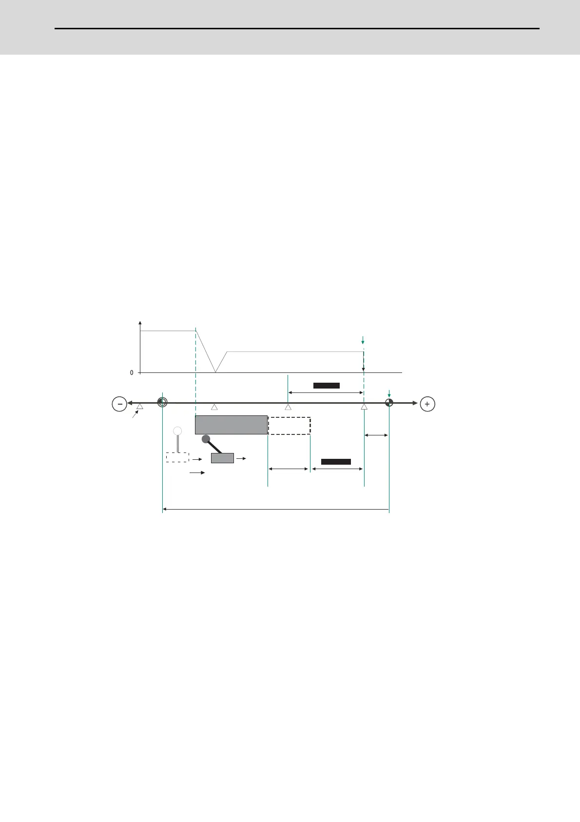
[Terms and parameters related to the dog-type reference position return]
Electrical zero point
The first grid point after the dog OFF.
If the grid point is at the position where the near-point dog is kicked OFF, the position of electrical zero point may be at
the grid point where the dog is kicked OFF or at the next grid point because of the delay of the limit switch operation. This
causes a deviation of reference position by the amount of the grid space.
Setting the grid mask amount ("#2028 grmask") prevents this deviation.
Reference position
The base for position and coordinate.
The axis is positioned to this position by the manual reference position return command or G28 command in the
machining program.
The position is determined by shifting from the electrical zero point by the amount of "#2027 G28sft Reference position
shift amount".
#2037 G53ofs
Grid space
Basic machine coordinate
system zero point
Axis speed
Reference position
(for the reference position return)
Position
Electrical zero point
#2026 G28crp
(G28 approach speed)
#2025 G28rap
(G28 rapid traverse rate)
Grid point
OFF
ON
Switch
#2028 grmask
Grid mask
amount
Grid amount
#2027
G28sft
Reference position
shift distance
#2030 dir (-)
(Reference position
return direction)
Near-point dog
Grid mask

 Loading...


