.
3.
SPECIFEATWNS
'-s,
/MELSEC=A
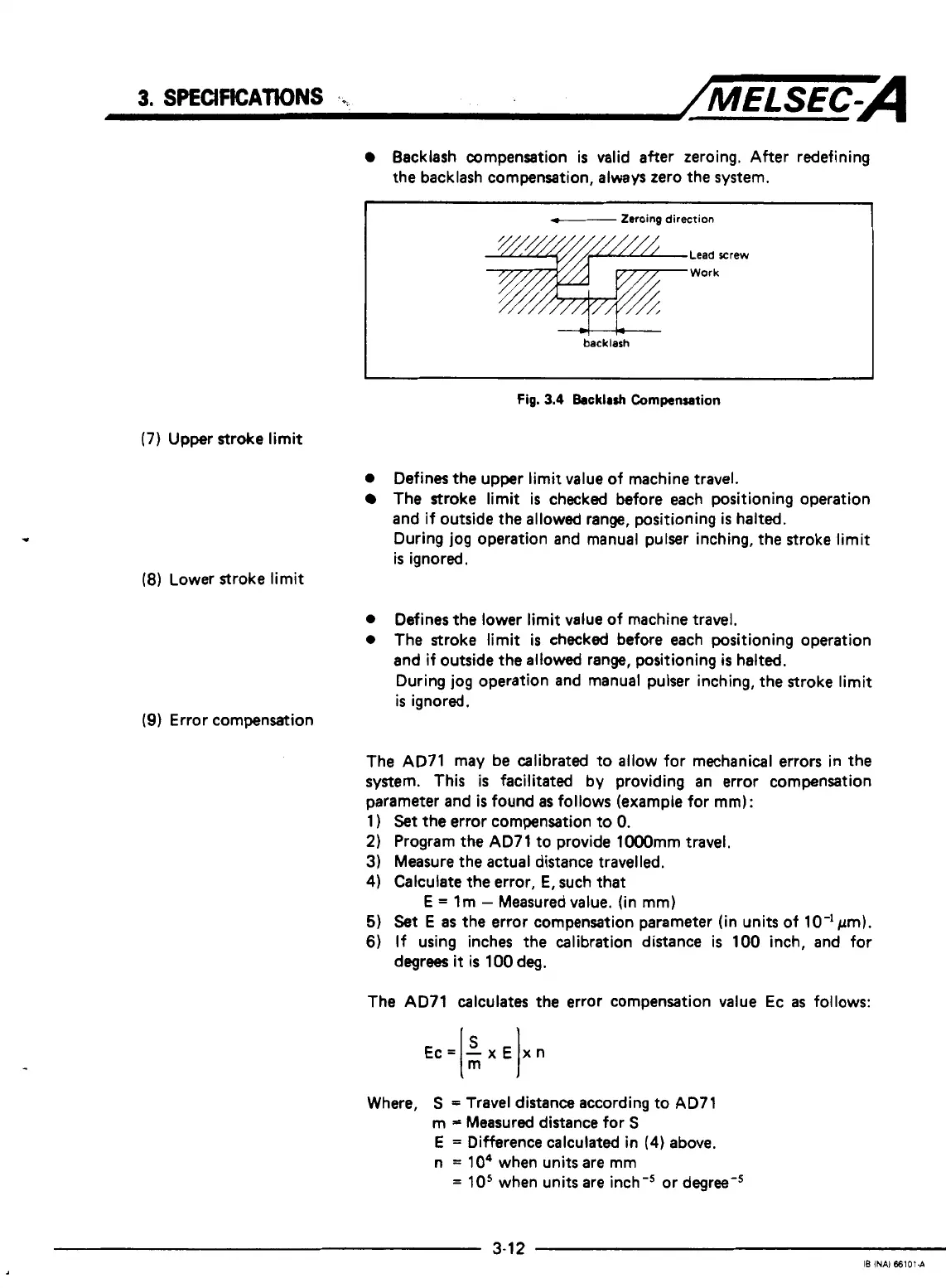
Backlash compensation
is
valid after zeroing. After redefining
the backlash compensation, always zero the system.
f--
Zeroing
direction
(7)
Upper stroke limit
Lead rrew
Work
-+t-+--
backlash
I
Fig.
3.4
Backlrsh
Cornpansation
0
Defines
the
upper limit value of machine travel.
The stroke limit is checked before each positioning operation
and if outside the allowed range, positioning
is
halted.
During jog operation and manual pulser inching, the stroke limit
is
ignored.
(8)
Lower stroke limit
0
Defines the lower limit value of machine travel,
0
The stroke limit
is
checked before each positioning operation
and if outside the allowed range, positioning
is
halted.
During jog operation and manual pulser inching, the stroke limit
is
ignored.
(9)
Error compensation
The AD71 may be calibrated to allow for mechanical errors in the
system. This
is
facilitated by providing an error compensation
parameter and
is
found
as
follows (example for
mm):
1
)
Set
the
error compensation to
0.
2)
Program the AD71 to provide lOOOmm travel.
3) Measure the actual distance travelled.
4)
Calculate the error,
E,
such that
5)
Set
E
as
the error compensation parameter (in units of 10-lpm).
6)
If using inches the calibration distance
is
100 inch, and for
E
=
lm
-
Measured value. (in
mm)
degrees
it
is
100 deg.
The AD71 calculates the error compensation value Ec
as
follows:
Ec=
-x€
xn
I:
I
Where,
S
=
Travel distance according to AD71
m
=
Measured distance for
S
E
=
Difference calculated in
(4)
above.
n
=
lo4
when units are mm
=
10'
when units are inch-' or degree-'
3-1
2
IB
INAI
66101-A

 Loading...


