3.
SPECIFKATIOMS
/MELSEC=A
0
In absolute mode positioning, positions are reached with refe
rence to
a
zero point address.
(See
Fig.
3.7.)
1
I
tom
point A
B
To
move
from
B
to A,
specify
address
70
as
the
destination ddreu
0
-
Address
70
Address
100
'
Fig.
3.7
Abduta
Method
0
To use
both
incremental
and
absolute modes in the Same axis
(e.g.
X
axis),
set
2.
In
this
case,
the mode
is
controlled by the
individual piece of positioning data. (Refer to Section
3.4.3
(page
3-23)
.)
i:
!*
(16)
M
code ON/OFF timing
M
codes are code numbers
(1
to
255)
assigned by the user to control
auxiliary functions
at
defined
points
in the positioning cycle.
These
are used by the
PC CPU
to co-ordinate
the
operation of external
equipment and processes.
0
M
code
use/non-use must
be
specified
as
well
as
where in the
positioning sequence they are to
be
used,
When
M
code non-use
is
specified or
A6GPP
test
mode
is
in
operation,
M
code
data in the buffer memory
is
cleared and the
"M
code
ON"
signal is not output.
0
"M
code
ON"
signal output
is
available in
two
timing modes,
WITH and AFTER.
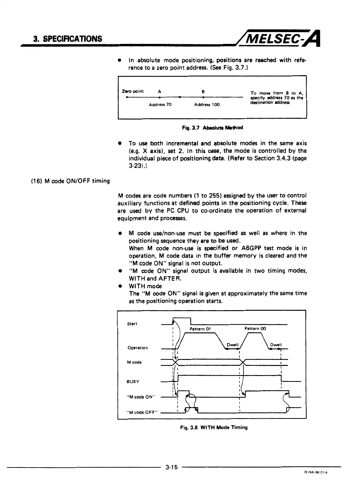
0
WITH mode
The
"M
code
ON"
signal
is
given
at
approximately the Same time
as
the positioning operation
starts.
I
Start
Pattern
00
I
I
I
I
Operation
"M
code
ON"
I
I
"M
code OFF"
Fig.
3.8
WITH
Mode
Timing
I
I
I
3-1
5
IB
INAI
66101.A

 Loading...


