.
.
3.
SPECIFICATIONS
/MELSEC=A
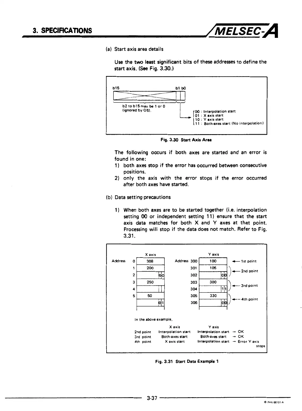
(a)
Start
axis
area details
Use
the two least significant bits of these addresses to define the
start
axis.
(See
Fig.
3.30.)
b15
bl
bo
I---=--------=!
.-
I
I
b2
to
b15
rnav
be
1 or
0
I
I
(ignored
by
OS).
00
:
Interpolation start
01
:
X
axis start
I
10
:
Y
axis start
11
:
Both-axes start
(No
interpolation)
I
Fig.
3.30
Start
Axis
Area
The following occurs if both axes are started and an error
is
found in one:
1)
both axes stop if the error has occurred between consecutive
positions.
2)
only the axis with the error stops if the error occurred
after both
axes
have started.
(b) Data setting precautions
1) When both axes are to be
started
together
(Le.
interpolation
setting
00
or independent
setting
1
1)
ensure that the
start
axis data matches for both
X
and
Y
axes
at
that point.
Processing will stop if the data does not match. Refer to Fig.
3.31.
X
axis
Y
axis
Address
0
[T
Address 300
-1
t
1st point
303
304
305
306
c-
c-
3
rd
4th
point
Doint
In
the
above example.
X
axis
Y
axis
2nd
point
Interpolation start Interpolation start
-t
OK
3rd point
Both-axes start Both-axes start
-
OK
4th point
X
axis start
Interpolation start
-
Error
Y
axis
stops
Fig.
3.31
Start Data Example
1
!
1
3-37
IB
INAl
66101-A

 Loading...


