117
2
3
4
5
6
7
8
3.9 Operation when the OUT, SET/RST, or PLS/PLF Instructions Use the Same Device
[Timing Chart]
• The ON/OFF timing of the X0 and X1 is different. (The specified device does not turn ON throughout the scan.)
• The X0 and X1 turn ON from OFF at the same time.
When using a refresh type CPU module and specifying output (Y) in the PLS instructions, the ON/OFF status of the
device at the execution of the last PLS instruction in the scan is returned as the output (Y).
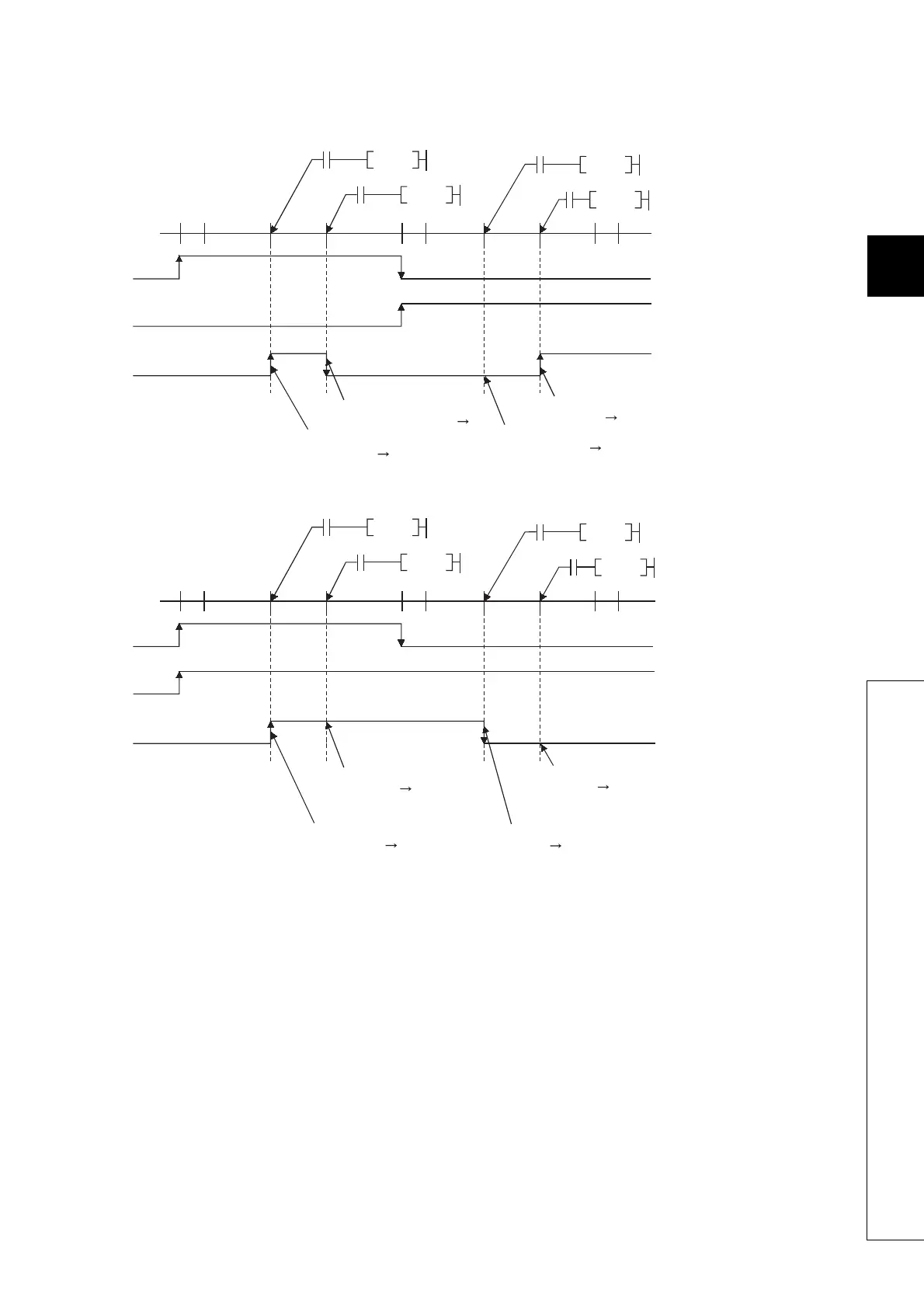
(4) PLF instructions using the same device
The PLF instruction turns ON the specified device when the execution command is turned OFF from ON.
It turns OFF the device at any other time (OFF to OFF, OFF to ON, or ON to ON).
If two or more PLF instructions using the same device are executed in one scan, each instruction turns ON the device
when the corresponding execution command is turned OFF from ON and turns OFF the device in other cases.
For this reason, if multiple PLF instructions using the same device are executed in a single scan, a device that has been
turned ON by the PLF instruction may not be turn ON during one scan.
M0
OFF
ON
END
END
END
X0
X1
M0
OFF
OFF
ON
PLS
X0
X1
M0PLS
M0PLS
M0PLS
X0
X1
ON
ON
M0 turns OFF because X1
status is other than OFF ON.
M0 turns ON because X1
goes ON (OFF ON).
M0 turns OFF because X0 status
is other than OFF ON.
(M0 remains OFF.)
M0 turns ON because
X0 goes ON (OFF ON).
M0
OFF
ON
END
END END
X0
X1
M0
OFF
OFF
ON
PLS
X0
X1
M0PLS
M0PLS
M0PLS
X0
X1
ON
M0 turns ON because
X0 goes ON (OFF ON).
M0 turns ON because X1
goes ON (OFF ON).
(M0 remains ON.)
M0 turns OFF because X1 status is
other than OFF ON.
(M0 remains OFF.)
M0 turns OFF because X0 status is othe
than OFF ON.

 Loading...

