560
SCL, SCLP, DSCL, DSCLP
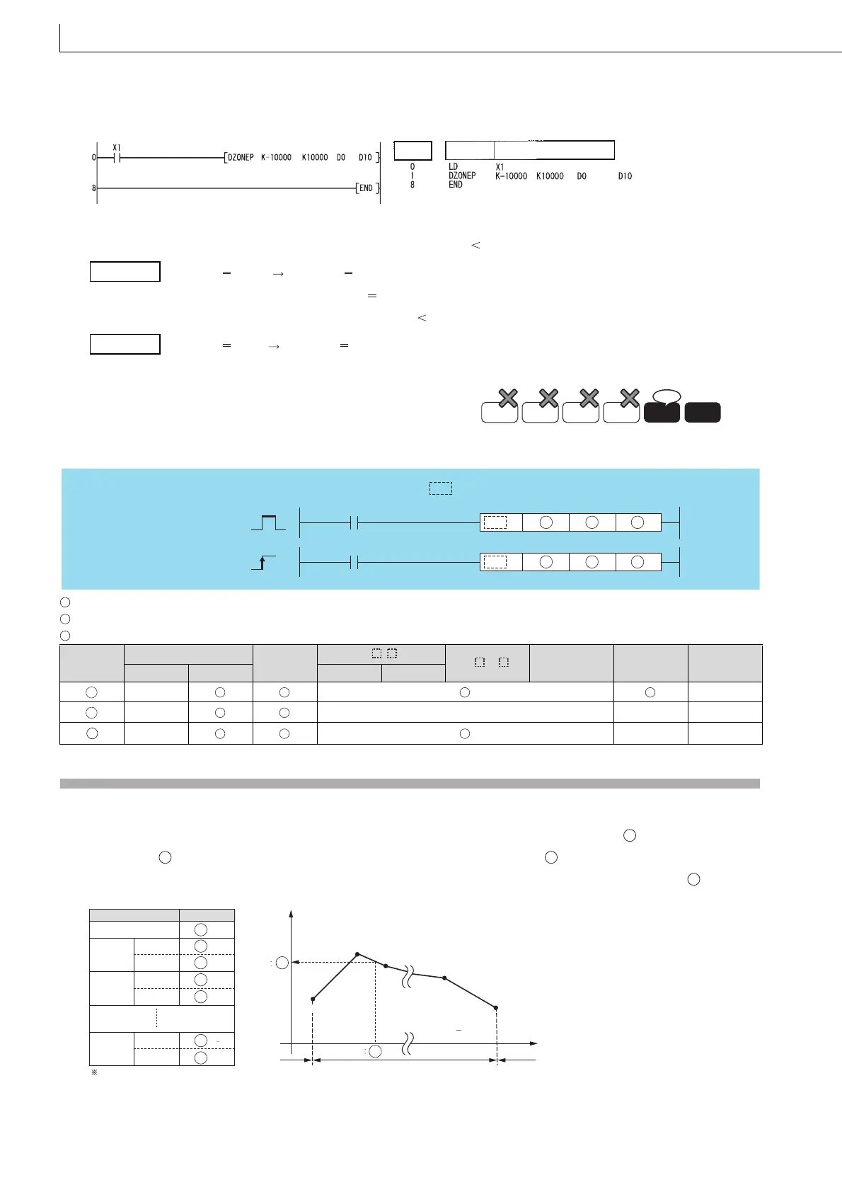
(2) The following program performs zone control by applying negative and positive bias values of -10000 to 10000 for the
data set at D0 and D1 and stores the result of control at D10 and D11 when X1 is turned ON.
[Ladder Mode] [List Mode]
[Operation]
• The value (D1, D0) + (-10000) is stored at (D11, D10) if (D1, D0) 0.
(D1,D0) -12345 (D11,D10) -22345
• The value 0 is stored at (D11, D10) if (D1, D0) 0.
• The value (D1, D0) + 10000 is stored at (D11, D10) if 0 (D1, D0).
(D1,D0) 50000 (D11,D10) 60000
: Input values for scaling or head number of the device where input values are stored(BIN 16/32 bits)
: Head number of the devices where scaling conversion data are stored(BIN 16/32 bits)
: Head number of the devices where output values depending on scaling are stored(BIN 16/32 bits).
Function
SCL(P)
(1) This instruction executes scaling for the scaling conversion data (16-bit data units) specified by with the input value
specified by , and then stores the operation result into the devices specified by .
The scaling conversion is executed based on the scaling conversion data stored in the device specified by and up.
7.13.4 SCL, SCLP, DSCL, Scalin g (Coordinate data by point)
DSCLP
7.13.4
SCL, SCLP, DSCL, DSCLP
• QnU(D)(H)CPU, QnUDE(H)CPU: The serial number (first five
digits) is "10102" or later.
Setting
Data
Internal Devices
R, ZR
J\
U\G
Zn
Constants
K, H
Other
Bit Word Bit Word
–– ––
–– –– –– ––
–– –– ––
Step
Instruction
Device
Example
Example
Basic
High
performance
Process
Redundant
Universal
LCPU
Ver.
SCL, DSCL
D
S2S1
SCLP, DSCLP
DP
S2S1
Command
Command
indicates an instruction symbol of
SCL/DSCL.
S1
S2
D
S1
S2
D
S2
S1
D
S2
Scaling conversion data component
Setting item
Device assignment
Number of coordinate points
Point 1
X coordinate
Y coordinate
X coordinate
Y coordinate
Point 2
X coordinate
Y coordinate
Point n
S2
S2 +1
S2 +2
S2 +3
S2 +4
S2 +2n 1
S2 +2n
Y
Output
value
D
Input value S1
Point 2
Point 3
Point n 1
Point n
Point 1
X
Operable range Operation erro
Operation error
n indicates the number of coordinates
specified by (S2).

 Loading...

