4 DATA INUPUT/OUTPUT
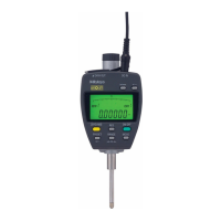
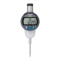
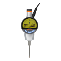
This chapter explains the data input/output methods of the Digimatic
indicator.
4
This instrument provides two data communication methods of SPC (Digimatic)
input/output and RS-232 input/output. Select one of these methods to use the data
communication function.
IMPORTANT
•
•
Use only the output cable of Mitutoyo specific accessories. The use of an improper
cable or deteriorated cable may disable data output.
Prior to data output carefully read the user’s manual of the data processing unit to use
it correctly.
4.1 SPC (Digimatic) Input/Output
Connect this instrument with a data processing unit such as Digimatic Mini Processor
DP-1VR using the M-SPC cable (optional accessory) to perform measurement transfer
and data processing including tabulation and record. It is also possible to input the preset
value by using Digimatic Presetter (option).
4.1.1 Connecting procedure
1 Switch the input/output format to SPC in the Parameter Setup mode. (Refer to section
3.2.)
2 Remove the cap on the I/O connector, and then plug the cable into the connector
firmly. (Pack the removed cap in a small bag and store it in a safe place so as not lose
it.)
TIP
• For the method of switching the input/output format, refer to the section “3.2 Parameter
Setup Mode”.
4.1.2 I/O connector
Pin# Signal I/O
1 GND -
2(*1) DATA1 O
3(*1) CK O
4 (*1) RD O
5(*2) REQ I
6(*3) ENTRY I
7(*3) DATA2 I
8 VDD(5V) O
9 (N.C) -
10 GND -
*2
*3
*1
NPN open-collector or
Nch open-drain circuit
(2SC2855, etc.)
External device side
1000pF
1kΩ
22kΩ
ID-H side
For the Vcc=5 system
R1,R2=22kΩ±10%
C=330pF±20%
Tr
5V
R2
C
Vcc
R1
74HC14, etc.
*3: ENTRY and DATA2 are terminals dedicated to the Digimatic Presetter.
IMPORTANT
• Since the power voltage differs between the ID-H and external device sides, absolutely
No. 99MAH016B
4-1

 Loading...
