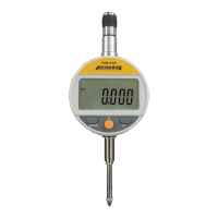
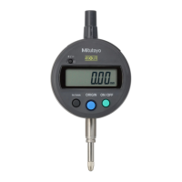
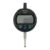
2 INSTALLATION
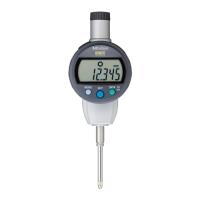
This chapter explains how to mount this Digimatic indicator on a
stand or a jig and how to attach or replace optional accessories.
2.1 Attaching the Clamp Filter
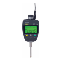
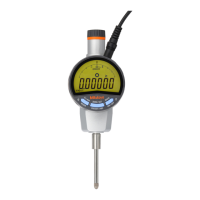
Use this instrument by wrapping the AC adapter cord around the clamp filter (ferrite core)
as shown in the figure below.
2.2 Mounting on a Stand or a Jig
Use this instrument with its stem being clamped on the comparator stand (option) or an
appropriate jig.
ossible, avoid fixing the stem by directly clamping it with a clamp screw, etc. If the em stem
clamped with a tightening torque of 300N•cm or more, the indicator could cause a
lfunction.
• Clamp the stem so that the spindle is oriented perpendicularly with respect to the
reference plane and a measuring surface. If the axis line (spindle) is not perpendicular
to the reference plane (measuring surface), an error is added to a measured value.
For example, assuming a tilt angle of the axis line from the reference plane as ψ, error δ
per measuring length 30mm will be the following according to the tilt angle: ψ = 1°: δ =
0.0045mm, ψ = 2°: δ = 0.0185mm, and ψ = 3°: δ = 0.0410mm.
• To mount this indicator on a jig, it is recommended that the stem be clamped with a
slotted holder that has a coupling portion of approximately φ8G7 (AGD: φ9.52) +
0.02/+0.005mm.
2.3 Attaching the Lifting Lever
While holding the spindle from the counter side (B) so as not to bend it, engage the
spindle with the groove on the lifting lever (No.137693/standard accessory).

 Loading...
