1
1
NAME OF RACH PART
This chapter describes the name of each part and the LCD display
contents.
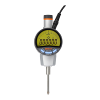
1.1 Part Names of the Main Unit
7
1 6
8
9
2
10
11
12
13
14
3
4
5
(1) Cylinder
(2) Lug mounting screw
(3) Stem
(4) Spindle
(5) Contact point
mm Type : Parts No.901312
inch Type : Parts No.21BZB005
(6) DC jack
(7) I/O connector
(8) Power switch
(9) LCD unit
(10)
Remote control reception
(11) MODE key
(12) SET/ZERO key
(13) DATA/Fn. key
(14)
Release attaching hole
(15) AC adapter
(16) Spindle lifting lever
(17) Clamp filter
16
15
17
NOTE
• Be sure to attach the clamp filter (ferrite core) to the AC adapter. For detailed
information about attachment, refer to section “2.1 Attaching the Clamp Filter”.
1-1
No. 99MAH016B
 Loading...