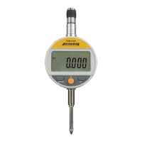
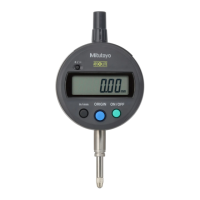
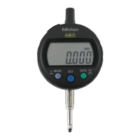
use an open-collector output circuit or open-drain output circuit on the external device
side. Do not use a CMOS output circuit.
• Pin 8 is a terminal dedicated to the RS-232 communication. It is not possible to
transmit from the external device or transmit to it.
4.1.3 Output data format (DATA1)
NOTE
• Up to 6 digits of numeric values can be outputted as the SPC (Digimatic) output. If the 7
digits of numeric value such as “123.4565mm” is outputted, for example, the instrument
output the SPC data as “23.4565mm”.
4.1.4 Timing chart
0.7ms < T1 < 1.2ms
100μs < T2 < 200μs
200μs < T3 < 300μs
100μs < T4 < 200μs
T5:
It depends on the capacity of
the data processing device
connected.
T
5
T
2
T
3
T
4
T
1
REQ
DATA
CK
RD
T
5
T
2
T
3
T
4
T
1
REQ
DATA
CK
RD
IMPORTANT
• If the output request (REQ) signal is received during the spindle displacement or if
the inverter receives output request (REQ) signals repeatedly at short intervals, the
instrument may not output data.
NOTE
• Retain the REQ signal at Low level until the CK signal is outputted. Also, return the
REQ signal to High level before the last CK signal (at the 52nd bit) is outputted.
4.1.5 Using the Digimatic Presetter
This instrument allows a preset value and upper/lower limit value to be set externally using
the Digimatic Presetter (Order No.543-003/option). The operating procedures are
described in the Presetter User’s Manual. However, the following operations differ from
the description in the manual. When using the Presetter be careful of the following points
besides reading that manual thoroughly.
1 When the setting of an upper limit value from the Presetter is complete, this
instrument is put in a wait state for successive input of a lower limit value.
Successively set a lower limit value from the Presetter.
No. 99MAH016B
4-2

 Loading...
