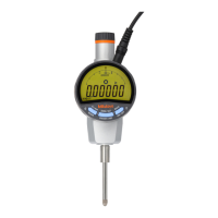
4.2 RS-232 Input/Output
Connect this instrument with an external device such as a PC using the RS-232 dedicated
cable (optional accessory). With this connection it is possible to perform initial setup of the
instrument, control of switching a measurement mode, etc., and processing such as
measurement data transfer.
Also, multiple Digimatic indicators can be controlled from one RS-232 port on the external
device by setting ID No. on each indicator.
4.2.1 Connecting procedure
1 Switch the I/O format to RS-232 in the Parameter Setup mode, and then set the
communication speed (baud rate), parity, and data bit according to the used external
device. (Refer to section 3.2.)
2 Replace the input/output connector cap and plug the cable securely. (The replaced
cap should be kept in a small bag to prevent losses.)
NOTE
• If data input/output is not performed properly, there is a possibility of an error in
communication setup. Check the settings of this instrument and the connected device.
TIP
• For the method of switching the input/output format, refer to the section “3.2 Parameter
Setup Mode”.
4.2.2 I/O connector
Connector specification: D-sub 9-pin female (receptacle)/inch thread specification
Pin# Signal I/O Definition
1 (N.C) - -
2 TxD O Transmit data
3 RxD I Receive Data
4 DSR I Data Set Ready
5 S.G - Signal Ground
6 DTR O Data Terminal Ready
7 CTS I Clear to Send
8 RTS O Request to Send
9 (N.C) - -
NOTE
• The above table lists the pin assignment of the dedicated cable connector.
4.2.3 Communication specification
Item Specification
Home position
DCE (Modem definition),
Dedicated cable must be used.
Compliant standard EIA/TIA-232F (RS-232)
Communication method Half duplex
Communication speed (bit rate) 4800 or 9600 bps
Data length 7 or 8bit / ASCII / Upper case
Parity control None, even, or odd
Stop bit 2 bit
Control signal CTS, DSR, or no control sequence
TIP
• For information about the switching method of bit rate, data length, and parity control,
refer to section 3.3.
No. 99MAH016B
4-4
 Loading...