Connectors and Cables Cha
ter Two: Installation
32
Connectors and Cables
The 247 unit’s two Interface connectors and four MFC connectors are located on the rear panel of
the unit (refer to Figure 6, page 43).
When the 247 is purchased as part of a complete system including MFCs, all of the required
interface cables are supplied. When purchased separately, the interface cables must be
specifically ordered. The system interface cables are listed in Table 5, page 20.
Interface Connector P6 (Channels 1 to 4)
The 25-pin male Type “D” connector, located on the rear panel (refer to Figure 6, page 43)
provides the communications link to and from the unit, including the connection to the scaled
transducer outputs, the lines to turn the flow on and off, and the set point input lines which
remotely set the flow rate of the MFCs.
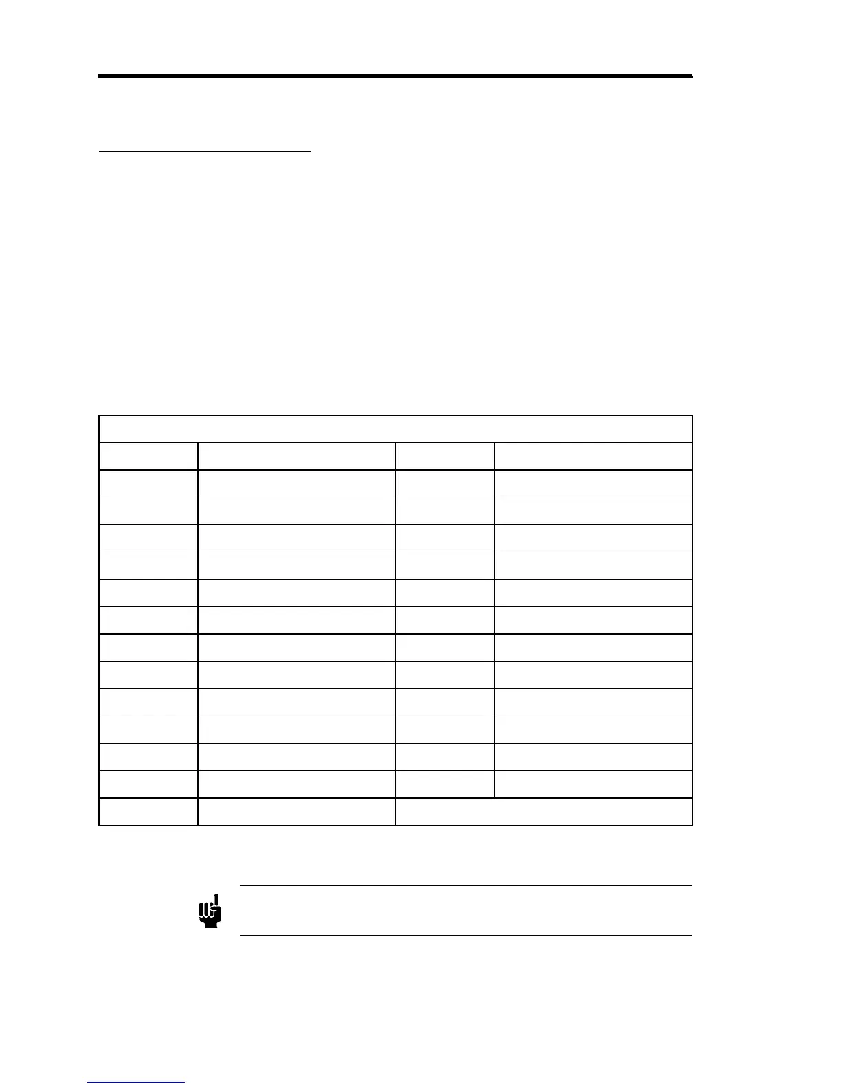
Interface Connector P6 (Channels 1 to 4) Pinout
Pin Assignment Pin Assignment
1 Signal Ground 14 Ch. 2 Transducer Output
2 Ch. 1 Transducer Output 15 Ch. 2 Scaled Output
3 Ch. 1 Scaled Output 16 Ch. 3 Transducer Output
4 Ch. 1 Set Point Input 17 Ch. 3 Scaled Output
5 Ch. 2 Set Point Input 18 Ch. 4 Transducer Output
6 Ch. 3 Set Point Input 19 Ch. 4 Scaled Output
7 Ch. 4 Set Point Input 20 No Connection
8 Digital Ground 21 No Connection
9 Power Ground 22 No Connection
10 Ch. 2 Flow ON/OFF Input 23 No Connection
11 Ch. 3 Flow ON/OFF Input 24 No Connection
12 Ch. 1 Flow ON/OFF Input 25 Chassis Ground
13 Ch. 4 Flow ON/OFF Input
Table 7: Interface Connector P6 (Channels 1 to 4) Pinout
Note
The “No Connection” pin assignment refers to a pin with no internal
connection.