Chapter Four: Operation External Flow Control
67
How To Setup the Controller for Pressure Control
Any controller that provides a positive signal with increasing flow (correct polarity) may be used;
the MKS Type 250 Pressure/Flow Controller is used for example only.
1. Verify that the LINE VOLTAGE SELECTOR SWITCH on the 250 controller is set to
the proper voltage.
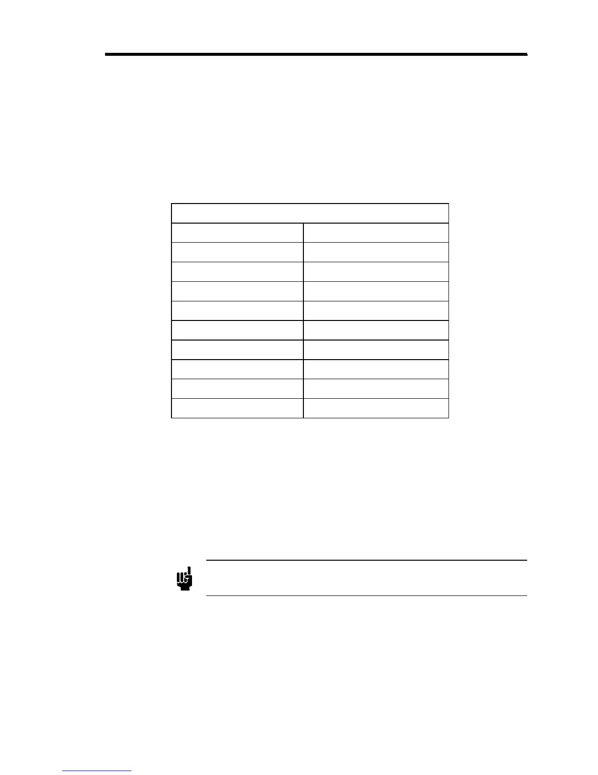
2. Set the FRONT PANEL CONTROLS on the 250 controller as listed in Table 16.
External Controller - Front Panel Controls
Control Position
Power Switch OFF
INT/EXT INT
10V/1V/.1V 10V
Phase Lead 1.5 SEC
Gain 20%
Bias Fully CCW
CMAE Manual
Manual Control 500 out of 1000
Set Point Level Required pressure level
Table 16: External Controller - Front Panel Controls
The settings in Table 16 configure the controller to deliver a constant Pressure Control
Signal (PCS) of approximately +5 V to the 247 unit’s External Ratio Amplifier. This
manually produced signal is used to determine if the required pressure and flow rates can
be achieved using a PCS with a nominal value of +5 V.
Best control performance is
achieved when the PCS is kept high for a good signal to noise ratio
.
3. Plug the AC LINE CORD into the power line and turn on the power switch.
Note
Allow the controller to warm-u
for at least 1½ hours before ad
ustin
the
zero.
4. Pump the chamber down below the resolution of the transducer and adjust the zero for a
reading of ±0000 on the controller’s Digital Panel Meter.
On controllers without a DPM, adjust the Set Point Control to zero and adjust for a zero
reading on the Error Meter.