Chapter Two: Installation Connectors and Cables
33
Interface Connector P5 (Channel 1)
The 9-pin Type “D” connector, located on the rear panel (refer to Figure 6, page 43), is used to
join two 247 units, or to connect a 247 unit to an external controller which provides the external
ratio signal interface.
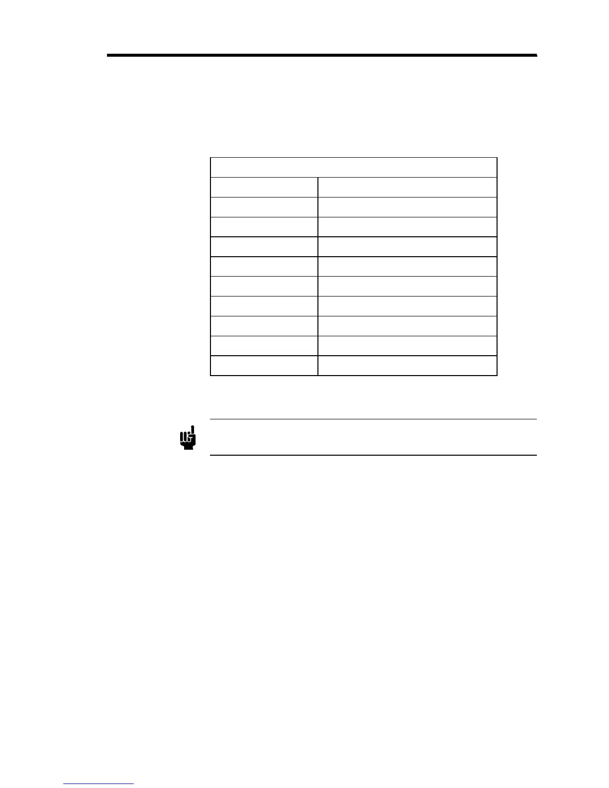
Interface Connector P5 (Channel 1) Pinout
Pin Assignment
1 Signal Ground
2 Ch. 1 Scaled Output
3 Digital Ground
4 Power Ground
5 No Connection
6 Ch. 1 Transducer Output
7 External Ratio Set Point Input
8 Ratio Output Voltage
9 Chassis Ground
Table 8: Interface Connector P5 (Channel 1) Pinout
Note
The “No Connection” pin assignment refers to a pin with no internal
connection.