External Flow Control Cha
ter Four: O
eration
64
How To Change the Dipswitch Settings
The External Ratio Amplifier will accept signals corresponding to a full scale voltage of +5 V or
+1 V. Configuring dipswitch S15 to the settings listed in Table 14, page 64, or Table 15, page
65, configures the RATIO position on all of the SET POINT SOURCE SWITCHES to be driven
by the output of the External Ratio Amplifier, rather than the +5 V internal reference.
The 247 unit is initially configured so that the set point signal is based on the Transducer Output
of Channel 1, with dipswitch S15 set as listed in Table 13.
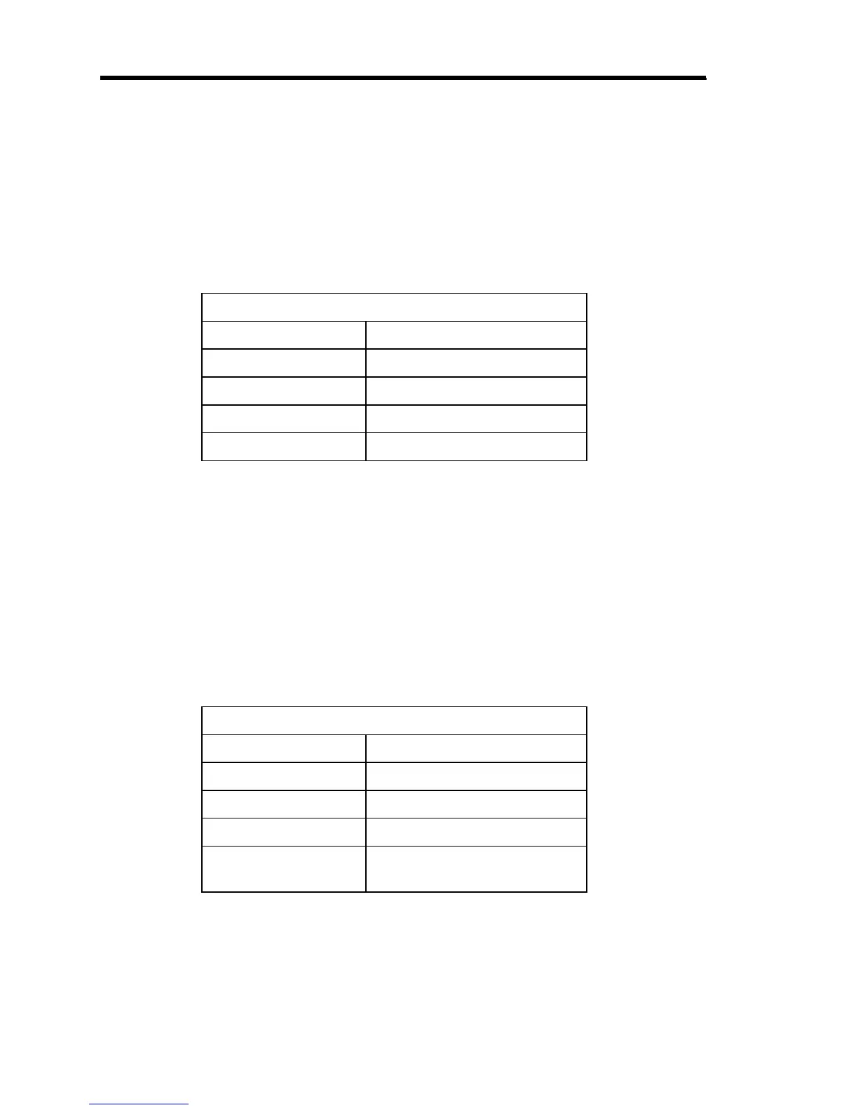
Dipswitch S15 Initial Settings
Dipswitch Position
1 Closed (On)
2 Open (Off)
3 Open (Off)
4 Open (Off)
Table 13: Dipswitch S15 Initial Settings
To change the dipswitch settings for external set point control:
1. Remove the retaining screws and the top cover of the 247 unit.
2. Locate the Main PC board.
3. Locate the 4-position dipswitch (S15) at the rear of the Main PC board.
4. To configure the 247 unit to accept +5 V full scale input, set dipswitch S15 to the
positions listed in Table 14.
Dipswitch S15 Settings for +5 V Full Scale Input
Dipswitch Position
1 Open (Off)
2 Closed (On)
3 Open (Off)
4 Open (Off)
(amplifier is set to unity gain)
Table 14: Dipswitch S15 Settings for +5 V Full Scale Input.