Chapter Three: Overview Rear Panel Controls
43
Rear Panel Controls
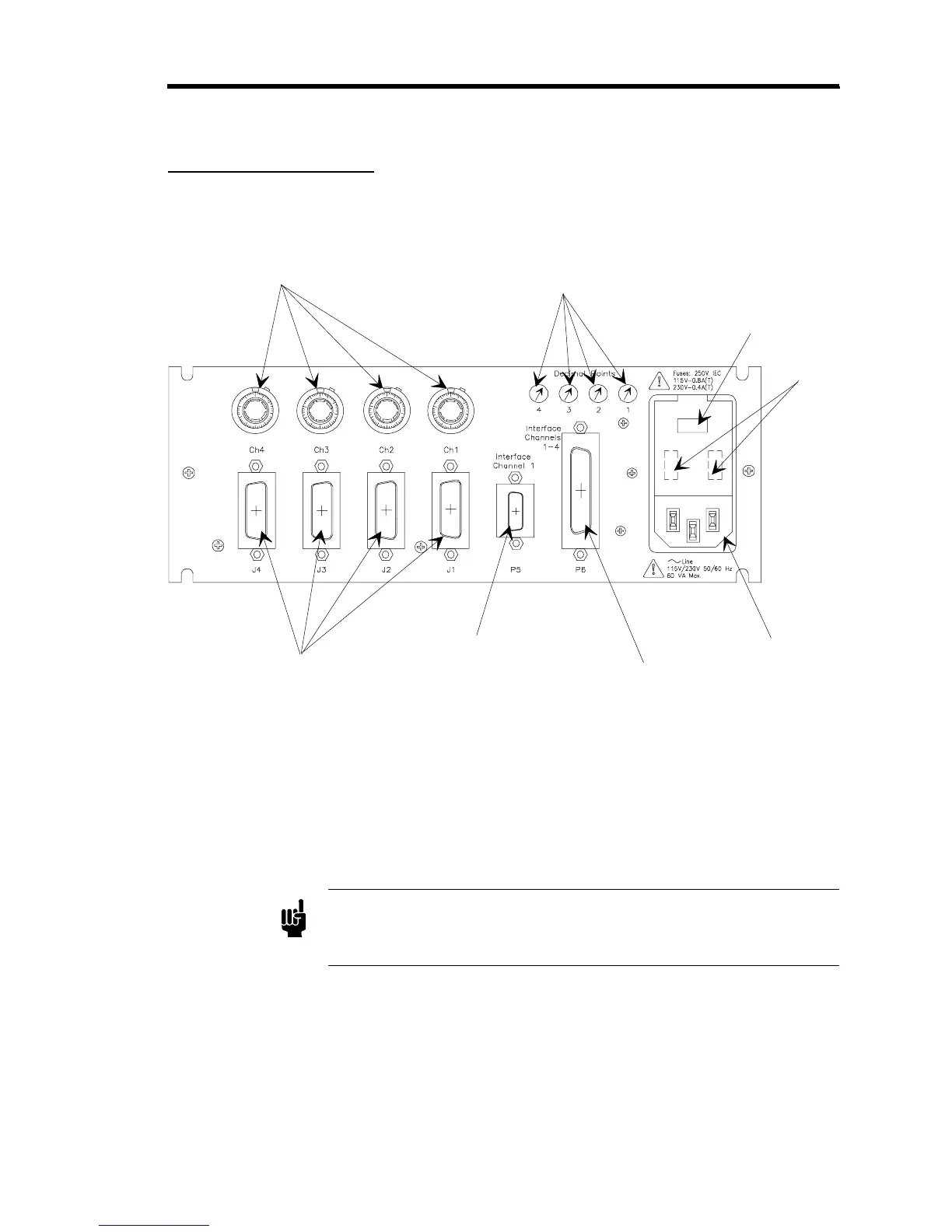
Figure 6 shows the location of the controls on the rear panel of the 247 controller.
Scalin
Controls
Decimal Point
Selector Switches
Line Volta
e
Selector
Fuse
MFC Connectors
J1 - J4
Interface Connector J5
Channel 1
Interface Connector J6
Channels 1- 4
AC Line Cord
Figure 6: Rear Panel Controls
Scaling Control Potentiometers
These four 10-turn potentiometers are used to enter the scaling factor, which scales down the
+5 VDC transducer output signal so that the Digital Panel Meter displays the flow rate and set
point directly in sccm or slm.
Note
It is
critical
for proper system operation that the scaling factors are
calculated properly and that the potentiometers are set correctly. Refer to
Scaling Controls
, page 46, for more information.