Chapter Four: Operation Manual Flow Control
61
How To Manually Control Ratioed Gas Flows
This mode of operation enables you to control the individual flow rates of Channels 2 to 4 as a
fraction of the flow of Channel 1, using an internal set point signal. The set point signal is
controlled by the Transducer Output of Channel 1.
If more than three channels are to be ratioed to Channel 1, a second 247 unit is required. The
second 247 unit must be connected to Channel 1 of the first 247 unit, and its S15 dipswitch must
be set for External Ratio Control. Refer to
How To Change the Dipswitch Settings
, page 64, for
more information.
Note
The MFC that is set to control at the highest percentage of its rated flow
should be connected to Channel 1.
In the following example, we will assume a system with four 100 sccm MFCs flowing nitrogen
(N
2
) gas. Channels 2 to 4 will be set to a ratio of 75, 50, and 25% of the flow in Channel 1.
1. Set the SET POINT SOURCE SWITCHES for Channels 1 to 4 to the FLOW position.
This connects an internal +5 V reference to the top of the SET POINT CONTROL.
Since the +5 V corresponds to full rated flow, each Set Point Control can be adjusted up
to a maximum of 100% for the attached MFCs rated flow.
2. Adjust the SET POINT for
each
MFC.
Hold the READ/SET POINT SWITCH in the SET POINT position and turn the SET
POINT CONTROL for each MFC to the level shown in Table 12, as displayed on the
Digital Panel Meter.
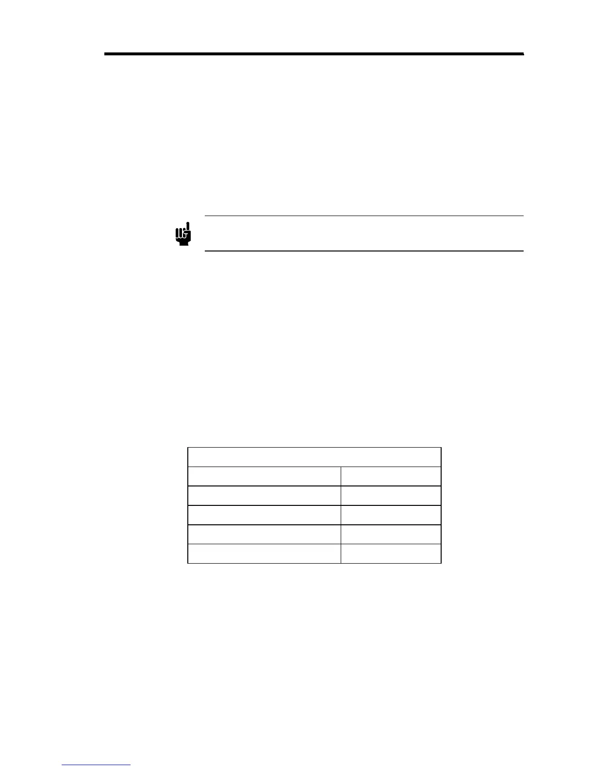
Ratio Control Set Point Levels
Set Point Control Level (SCCM)
Channel 1 0 to 100
Channel 2 75
Channel 3 50
Channel 4 25
Table 12: Ratio Control Set Point Levels
When the adjustment is complete, release the READ/SET POINT SWITCH; it is spring
loaded and will return to the READ (Flow) position.
Since the Digital Panel Meter is driven from the scaled output, the displayed value has
the Gas Correction and Gauge Factors applied
. Therefore, it represents the actual set
point in sccm for the attached MFC
. Refer to
Scaling Controls
, page 46, for more
information.