RS-232 Messages Cha
ter Six: RS-232 Communications O
tion
96
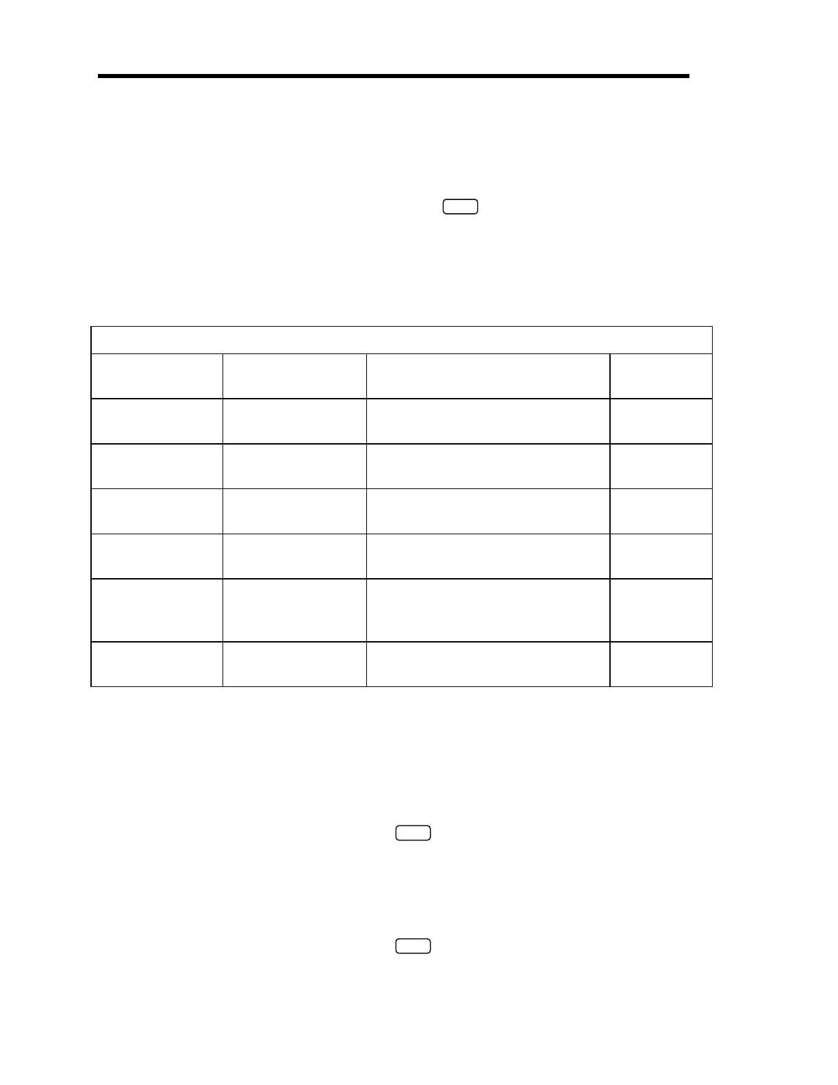
Trip Point Messages
The Trip Point messages, listed in Table 23, require the <id> entry to identify the trip point:
@parameter
id
data
ENTER
where:
id
= 0 for Trip Point A
= 1 for Trip Point B
Refer to
The [TRIP POINTS] Key,
page 54, for a complete description of the trip points.
Trip Point Messages
Parameter Entry Action
Data
for a Command
Data
for a
Request
40 High Trip Point ASCII number ranging from -105%
to +105% of transducer full scale
‘?’
41 Low Trip Point ASCII number ranging from -105%
to +105% of transducer full scale
‘?’
42 Trip Point Hysteresis ASCII number from 0 to 10 (used as
a % of trip point value)
‘?’
43 Relay Normal
Configuration
0 = De-energized
1 = Energized
‘?’
44 Trip Point Channel 0 = Channel 1
1 = Channel 2
2 = Channel 3
‘?’
45 Latch Mode 0 = Disabled
1 = Enabled
‘?’
Table 23: RS-232 Trip Point Messages
Example 1: How To Configure the Trip Point Values
1. To set the trip point high value for TP A to 900, issue the following command:
@400900
ENTER
The 670 instrument will return the same command to indicate that the command was
accepted and implemented.
2. To set the trip point low value for TP A to 450, issue the following command:
@410450
ENTER
Artisan Technology Group - Quality Instrumentation ... Guaranteed | (888) 88-SOURCE | www.artisantg.com


 To Next Page