Chapter Three: Hardware Overview Rear Panel
37
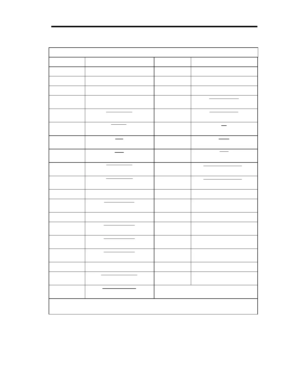
Pinout of the I/O Connector Pinout
Pin Number Assignment Pin Number Assignment
1 Trip Point A NC 20 Trip Point A Common
2 Trip Point A NO 21 Trip Point B Common
3 Trip Point B NC 22 Trip Point B NO
4 Digital Ground 23
x1 Range ID
5
x0.1 Select
24
x0.01 Select
6
Special
25
1
7
10
26
100
8
1K
27
10K
9
Latch TP B
28
Select Channel 2
*
10
Latch TP A
29
Select Channel 1
*
11 Reserved 30 +15 V
12
Remote Zero
31 -15 V
13 Reserved 32 Power Ground
14
Channel 3 ID
33 Reserved
15
Channel 2 ID
34 Reserved
16
Channel 1 ID
35 Analog Ground
17 Reserved 36 Pressure Output
18
x0.01 Range ID
37 Reserved
19
x0.1 Range ID
NC = Normally Closed NO = Normally Open
* The 274 multiplexer uses these pins select the active channel. Both pins 28 and 29 high when
Channel 3 is the active channel.
Table 9: Pinout of the I/O Connector
Artisan Technology Group - Quality Instrumentation ... Guaranteed | (888) 88-SOURCE | www.artisantg.com