Rear Panel Cha
ter Three: Hardware Overview
34
Serial Interface or IEEE-488 Connector
Slot 1 will contain either the Serial Interface or the IEEE-488 board, depending on which remote
communications option you ordered. The remote communications feature allows the 670
instrument to communicate with, and be controlled by, a computer equipped with the appropriate
communications software. To use a computer to control the 670 instrument, place the Key Lock
switch on the front panel of the 670 instrument in the
REMOTE
position.
Serial Interface (RS-232) Connector
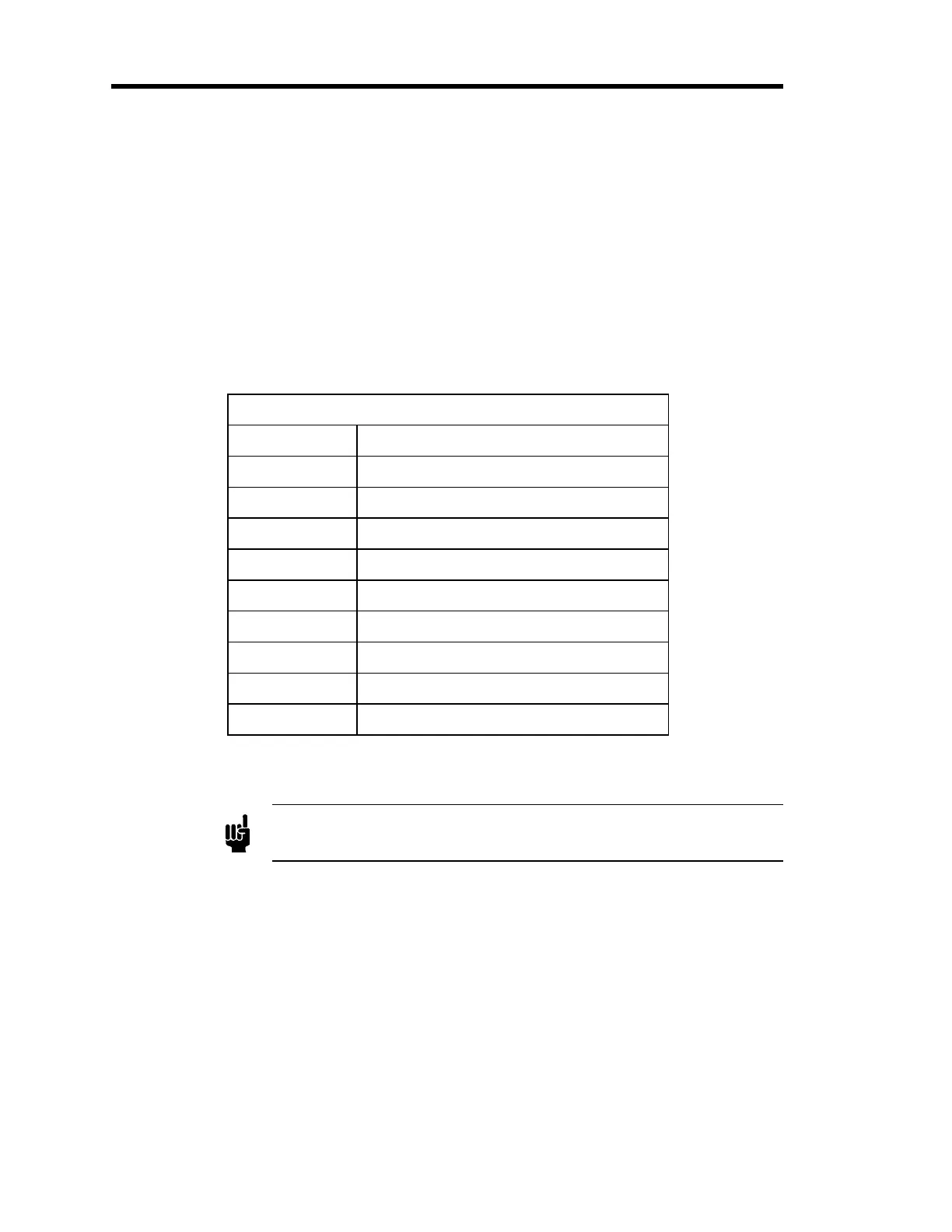
The Serial Interface connector is a 9-pin male Type “D” connector. The pinout of the connector
is listed in Table 7.
Pinout of the Serial Interface Connector
Pin Number Assignment
1 No Connection
2 Transmit Data
3 Receive Data
4 No Connection
5 Digital Ground
6 No Connection
7 No Connection
8 No Connection
9 No Connection
Table 7: Pinout of the Serial Interface Connector
Note
There is no internal connection on pins assigned a “No Connection”
function.
Artisan Technology Group - Quality Instrumentation ... Guaranteed | (888) 88-SOURCE | www.artisantg.com