Rear Panel Cha
ter Three: Hardware Overview
38
Signal Conditioner Board
The Signal Conditioner board provides the interface between the 670 instrument and the pressure
transducer. The board contains two connectors: an upper connector labeled “Head,” and lower
connector labeled “Signal.”
Head (Upper) Connector
The Head connector is a 15-pin female Type “D” connector that enables the 670 instrument to
connect to a pressure transducer. Refer to Table 10 for the pin assignments.
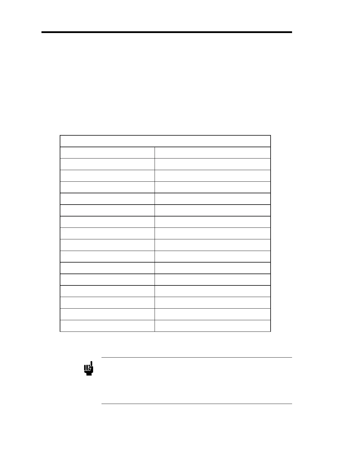
Pinout of the Head Connector Pinout (on the Signal Conditioner Board)
Pin Number Assignment
1 Chassis Ground
2 Analog Common
3 Heater Return (-38 V)
4 Mux Input
5 No Connection
6 Signal Return
7 Signal Input
8 Heater (+38 V)
9 -13 V
10 +13 V
11 No Connection
12 Reserved
13 Preamp (+12 V)
14 System Check
15 Oscillator (6 VAC)
Table 10: Pinout of the Head Connector on the Signal Conditioner Board
Note
1. A “No Connection” pin assignment refers to a pin with no internal
connection. A “Reserved” pin assignment means that the pin has an
internal connection and may be assigned a function in the future.
2. Use pin 1 to access the pressure output signal if your 670 instrument
is connected to a 274 multiplexer.
Artisan Technology Group - Quality Instrumentation ... Guaranteed | (888) 88-SOURCE | www.artisantg.com